Transistor Biasing Techniques & Stability with power supply 1KHz, Oscillator and 3 meters
Order Code: 36203
Category: Analog Electronics Trainers
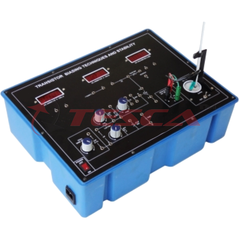
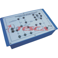
Experimental Training Board has been designed specifically to study different biasing techniques for transistor amplifier circuits. Also the effect of transistor replacement (change in b) and temperature changes can be studied on all biasing cir...
SPECIFICATION
Experimental Training Board has been designed specifically to study different biasing techniques for transistor amplifier circuits. Also the effect of transistor replacement (change in b) and temperature changes can be studied on all biasing circuits.
Practical experience on this board carries great educative value for R & D labs, Science and Engineering Students.
Object:
Practical experience on this board carries great educative value for R & D labs, Science and Engineering Students.
Object:
- Study of Q-point variation due to transistor replacement (Changes in b) in:
- Fixed-bias circuit.
- Collector to base bias circuit.
- Self bias (Emitter bias) circuit.
- Self bias (Emitter bias) in addition to voltage divider bias circuit.
- A qualitative comparison of the effect of temperature on bias stability of the above four biasing circuits.
Features:
The board consists of the following built-in parts:
- Two germanium NPN transistors one having low b and the other having high b.
- 12V DC at 100mA, IC regulated Power Supply.
- 1 KHz Sine Wave signal generators having 0-1 volt variable output level.
- D.C. Microammeter, 65mm rectangular dial to read 0-100mA, for base current measurement.
- D.C. Milliammeter, 65mm rectuangular dial to read 0-25mA, for collector current measurement.
- D.C. Voltmeter, 65mm rectangular dial to read 0-15V.
- Electric oven for heating up the transistor.
- Thermometer clamp for holding a thermometer. AThermometer of 0-100°C provided along with the unit.
- Adequate no. of other electronic components.
- Mains ON/OFF switch, Fuse and Jewel light.
- The unit is operative on 230V ±10% at 50Hz A.C. Mains.
- Adequate no. of patch cords stackable from rear both ends 4 mm spring loaded plug length ½ metre.
- Good Quality, reliable terminal/sockets are provided at appropriate places on panel for connections & observation of waveforms.
- Strongly supported by detailed Operating Instructions, giving details of Object, Theory, Design procedures, Report Suggestions and Book References.
Other Apparatus Required:
- Cathode Ray Oscilloscope 20MHz



 91-9829132777