Telecommunication Trainer
Order Code: 23247255.2
Category: General Lab Equipment IV
DSB SSB TRANSMITTER TRAINER Scope of learning : Study of carrier frequency generation. Study of DSB & SSB AM generation & Transmission. Study of Transmitter circuits. Study of Modulation index. Technical specifications : ...
SPECIFICATION
DSB SSB TRANSMITTER TRAINER
Scope of learning :
- Study of carrier frequency generation.
- Study of DSB & SSB AM generation & Transmission.
- Study of Transmitter circuits.
- Study of Modulation index.
Technical specifications :
On board :
- 8 Switched Faults.
- Crystal Controlled Carrier Frequency.
- On - board Audio Modulator,
- Carrier Frequency Generation,
- Antenna & Speaker.
Power supply :
- Fixed DC Power Supplies +15V DC, 250mA
- Operated on Mains power 230V, 50Hz +10%
Components mounted on the panel are :
- IC
- Capacitors
- Resistors
- Diode
Salient Features :
- Front panel built with high class insulated Printed Circuit Board sheet with well printed circuits and symbols.
- Instruction manual.
- Connections are brought out through 2mm Sockets.
- Patch Cords 2mm.
- The trainer is housed in ABS Plastic cabinet/Wooden Cabinet
- Size of the trainer set 12”x10”
Optional accessories :
- CRO
DSB SSB RECEIVER TRAINER
Scope of learning :
- Study of DSB & SSB AM reception & detection by diode /product detectors
- Study of AGC
- Study of Receiver tuned circuit
- Study of Sensitivity, Selectivity & Fidelity of Receiver
Technical specifications :
On board :
- Frequency Range : 980 KHz to 2.060 Mhz
- Intermediate Frequency (IF) : 455 Khz
- Input Circuits :
- RF amplifier
- Mixer
- Local oscillator
- Beat frequency oscillator
- IF amplifier 1
- IF amplifier 2
- Tuning: With variable capacitor (ganged) dial marking on board
- Power supply :
- Fixed DC Power Supplies +15V DC, 250mA
- Operated on Mains power 230V, 50Hz +10%
- Components mounted on the panel are :
- IC
- Capacitors
- Resistors
- Diode
- Salient Features : Front panel built with high class insulated Printed Circuit Board sheet with well printed
- circuits and symbols.
- Instruction manual.
- Connections are brought out through 2mm Sockets.
- Patch Cords 2mm.
- The trainer is housed in ABS Plastic cabinet/Wooden Cabinet.
- Size of the trainer set 12”x10”
FM TRANSMITTER AND RECEIVER TRAINER
Scope of learning :
- Study of Frequency Modulation using Varactor modulator
- Study of Frequency Modulation Using Reactance Modulator
- Study of Operation of Detuned Resonant Circuit
- Study of Operation of Quadrature Detector
- Study of Operation of Phase-Locked Loop Detector
- Study of Operation of Foster - Seeley Detector
- Study of Operation of Ratio Detector
Technical specifications :
On board :
- 8 switched faults.
- Audio Oscillator : With adjustable amplitude & frequency (300 Hz - 3.4 Khz)
- Two Types of FM Modulator:
- Reactance Modulator (with carrier frequency adjustment)
- Varactor Modulator (with carrier frequency adjustment)
- Mixer / Amplifier: Allows FM input signal to be amplitude modulated by a noise input prior to demodulation, with gain adjustment.
- Transmitter Output Frequency. : 455 Khz
- Five types of FM demodulator :
- Detuned Resonant Detector
- Quadrature Detector
- Foster - Seeley Detector
- Ratio – Detector
- Phase Locked Loop Detector
- Low Pass Filter Amplifier: 3.4 KHz cut off frequency. (with adjustable gain)
- Effect of noise on the detection of FM signal may be investigated.
- Power supply :
- Fixed DC Power Supplies +15V DC, 250mA
- Operated on Mains power 230V, 50Hz +10%
- Components mounted on the panel are :
- IC
- Capacitors
- Resistors
- Diode
- Salient features : Front panel built with high class insulated Printed Circuit Board sheet with well printed
- circuits and symbols.
- Instruction manual.
- Connections are brought out through 2mm Sockets.
- Patch Cords 2mm.
- The trainer is housed in ABS Plastic cabinet/Wooden Cabinet.
- Size of the trainer set 12”x10”
ANALOG SAMPLING AND RECONSTRUCTION TRAINER
- Scope of learning :
- Study the Sample signal and Sample/Hold signal and its reconstruction;
- Study the effects of different Sampling;
- Study the effects of 2nd and 4th Order low pass filters for the reconstruction of the
- signal frequencies on the reconstructed signal;
- Study the effects of Varying duty cycle of Sampling frequencies on the amplitude of the
- reconstructed signal
Technical specifications :
Generator :
- Crystal controlled pulse generator.
- Sine Wave Generator - Provides Synchronized Sine waveform output of Frequency 1 KHz & 2KHz.
- Pulse Generator-Switch selectable sampling frequency of 2,4,8,16, 32 Khz,
- Internal/ External sampling signal selectable
- Power supply :
- Fixed DC Power Supplies +12V,+5V DC, 250mA
- Operated on Mains power 230V, 50Hz +10%
- Components mounted on the panels are :
- IC
- Capacitors
- Resistors
- Diodes
- Salient features : Ront panel built with high class insulated Printed Circuit Board sheet with well printed
- circuits and symbols.
- Instruction manual.
- Connections are brought out through 4mm Sockets.
- Patch Cords 4mm.
- The trainer is housed in ABS Plastic cabinet.
- Size of the trainer set 12”x8”
DATA FORMATTING AND CARRIER MODULATION TRAINER
Scope of learning :
- Study of Coversion of NRZ data to other data formats NRZ(L), NRZ(M) RZ, AMI, RB, Biphase (Manchester), Biphase (Mark), Differentially encoded dibit pair
- Study of following Carrier Modulation Techniques and their comparison - ASK, FSK,PSK & QPSK
Technical specifications :
Generator :
- On-board Carrier generation circuit (Sine waves synchronized to transmitter data).
- On- board in phase and quadrate phase carrier for QPSK modulation. ? Different data conditioning formats NRZ (L), NRZ (M), RZ, Biphasic. (Manchester), Biphasic (Mark),
- AMI, RB, differentially encoded debit pair.
- FSK, PSK, ASK ,DPSK & QPSK carrier modulation. Variable carrier and modulation Off- Set. Variable carrier gain.
- On-board Unipolar to Bipolar conversion. On-board data inverter.
Power supply :
- Fixed DC Power Supplies +12V,+5V DC, 250mA
- Operated on Mains power 230V, 50Hz +10%
Components mounted on the panel are :
- IC
- Capacitors
- Resistors
- Diode
Salient features :
- Front panel built with high class insulated Printed Circuit Board sheet with well printed circuits and symbols.
- Instruction manual.
- Connections are brought out through 4mm Sockets.
- Patch Cords 4mm.
- The trainer is housed in ABS Plastic cabinet.
- Size of the trainer set 12” * 10”
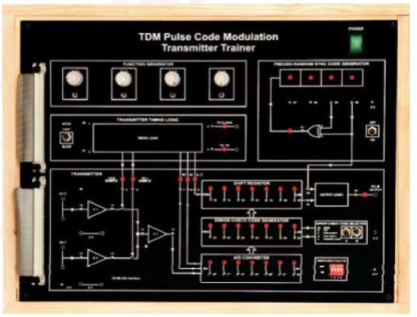
TDM PULSE CODE MODULATION TRANSMITTER TRAINER
Scope of learning :
- Study of Pulse Code Modulation. Study the principles of ADC &DAC Study of Pseudo Random Sequences
- Study of effect of faults in Modulation & Demodulation Techniques.
- Study of Error Check Code Logic:
- None Parity Coding.
- Odd Parity Coding
- Even Parity Coding
- Hamming Coding
Technical specifications :
- Crystal Controlled Clock.
- On-board Sine wave generator (Synchronized)
Power supply :
- Fixed DC Power Supplies +12V,+5V DC, 250mA
- Operated on Mains power 230V, 50Hz +10%
Components mounted on the panel are :
- IC
- Capacitors
- Resistors
- Diode
- PCM Transmitter.
- Fast & Slow modes for real time operation and data flow examination. Error check code options (odd-even parity, Hamming Code).
- 4 Switched faults allow different Error Check Options.
- PC - PC Communication via RS 232 interface
Salient Features :
- Front panel built with high class insulated Printed Circuit Board sheet with well printed circuits and symbols.
- Instruction manual.
- Connections are brought out through 4mm Sockets.
- Patch Cords 4mm.
- The trainer is housed in ABS Plastic cabinet
- Size of the trainer set 12”x10”
Optional accessories :
- CRO
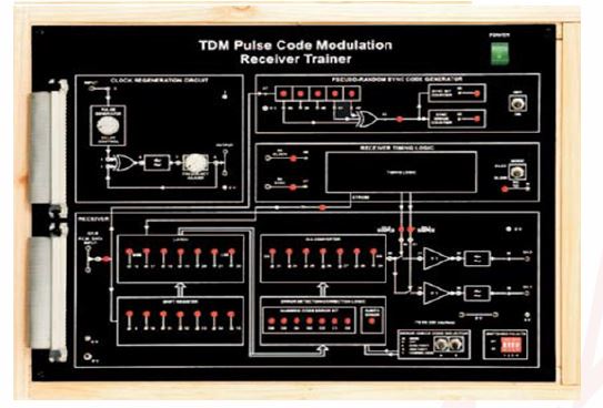
TDM PULSE CODE DEMODULATION RECEIVER TRAINER
Scope of learning :
- Study of PCM Demodulation Technique
- Study of Time Division Demultiplexing of PCM data
- Study of Clock Regeneration by PLL Study of Detection & Correction of Error induced by switched faults in the transmitter.
- Study of signal recovery in 3 connecting modes between transmitter & receiver
- Study of Importance of Clock and Frame Synchronization in PCM system Study of the effect of induced faults in receiver.
Technical specifications :
Generator :
- On board PLL for clock regeneration.
- On board sync code detector.
Power supply :
- Fixed DC Power Supplies +12V,+5V DC, 250mA
- Operated on Mains power 230V, 50Hz +10%
Components mounted on the panel are :
- IC
- Capacitors
- Resistors
- Diode
- Input accepts two channel multiplexed data. On board De-?multiplexed PCM Receiver.
- On board L.P. Filter.
- Fast & Slow modes for real time operation and data flow examination.
- Error check code options.
- Odd or Even Parity-?Single bit error detection.
Salient Features :
- Front panel built with high class insulated Printed Circuit Board sheet with well printed circuits and symbols.
- Instruction manual.
- Connections are brought out through 4mm Sockets.
- Patch Cords 4mm.
- The trainer is housed in ABS Plastic cabinet.
- Size of the trainer set 12”x10”
CDMA TRAINER
Scope of learning :
- To study theory of CDMA DSSS Modulation & Demodulation
- To generate CDMA-DSSS signal
- To demodulate CDMA-DSSS signal using BPS
- To study pseudo random bit sequence generation.
Technical specifications :
Generator :
- Direct Sequence Spread Spectrum (DSSS) generator and decoder
- Analog Modulators :
- Binary Phase Shift Keying (BPSK)Modulator
- Pulse Width Modulator
- Analog Demodulators :
- Binary Phase Shift Keying (BPSK) Demodulator
- Pulse Width Demodulator
Power supply :
- Fixed DC Power Supplies +12V,+5V DC, 250mA
- Operated on Mains power 230V, 50Hz +10%
Components mounted on the panel are :
- IC
- Capacitors
- Resistors





 91-9829132777