
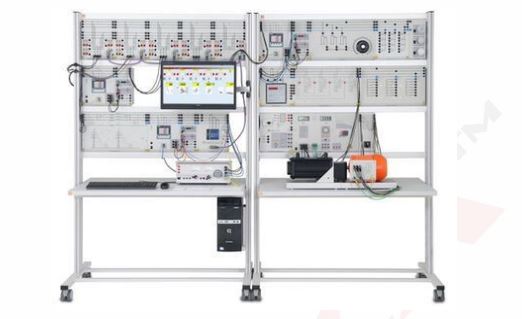
Smart Grid
Order Code: 24257587.9
Category: General Lab Equipment V
This system has 2 brushless Machine with their shaft ends are insulated built on an aluminium base with glides. The machine is to be operated on the machine bench. All connections are brought out on the overhead connection box separated on 4 mm safet...
SPECIFICATION
This system has 2 brushless Machine with their shaft ends are insulated built on an aluminium base with glides. The machine is to be operated on the machine bench. All connections are brought out on the overhead connection box separated on 4 mm safety plugs. The machine is protected against overload by a built-in stator winding temperature switch against overload. The nominal data is shown on three nameplates on the connection box. In addition to the protective conductor connection, a fastening for equipotential bonding line is provided via M6 thread on the connection box.
Brushless controller with motor
-
1kW power brushless motor with electronic encoder
-
Voltage --------400V
-
Frequency 50 Hz
-
Control of the system in frequency and voltage
-
Mechanical braking system for the analysis of the torque
-
Encoder outputs for the analysis of speed
-
Display system for controlling and monitoring events
-
Button start and stop action and automatic stop intervention in case of alarm.
-
Complete software for PC interfaced to the system via RS485.
Braking resistance
Three-Phase Asynchronous Motor
-
Power: 1.5 kW
-
Excitation voltage: minimum 127 V
-
Excitation current: minimum 4.9 A
-
Power factor: minimum 0.7
-
Voltage: 220/380 V Δ/Y
-
4 poles
-
Rated speed: 1500 rpm, 50 Hz
-
Type of construction: B3
-
Shaft end: 1
-
Base: Aluminium
-
Terminal box: Top
-
Temperature class: B (120°)
-
Degree of protection (IP): IP20
-
Temperature detectors: Bimetal switches 110° NC (normally closed)
Base
-
Didactic equipment: this item must consist of a steel alloy varnished structure mounted on anti-vibration rubber feet, provided with slide guides for the fixing of one or two machines and with a coupling guard.
-
Complete with a device for the locking of the rotor of the slip ring asynchronous machines in the short-circuit test.
-
Composition:
-
Light alloy base, leveled on the upper supporting planes, with two guides for all the couplings of machines rated 1 kW.
-
In the lower section high sensitivity shock absorbers must be mounted, arranged to be fixed to a supporting plane.
-
Removable butt strap in varnished plate.
-
Flask for the blocked rotor test in varnished light alloy.
Three-Phase Synchronous Machine
-
Didactic equipment
-
Machine with smooth inductor and three-phase stator armature winding for operation either as an alternator or as a synchronous motor.
-
Technical features:
-
Alternator: Power: 1.1 kVA - Motor:
-
Power: minimum 1 kW
-
Voltage: 220/380 V D/Y
-
Current: 2.9/1.7 A D/Y
-
Speed: 3000 rpm
-
Excitation: 175 V / 0.4 A
-
It must be possible to couple the electrical machine with other electrical machines through a hub and spider elastic gear ring in polyurethane. It must be supplied with a hooked module in aluminum with PVC label and safety terminals for the electrical connection. A schematic diagram must be shown on the hooked module.
-
Each machine must be mounted on a base and must be provided with: Plate that brings its axis height to the standard measure (112 mm). Plates for fixing to the base of the machine and Four screws for fixing of the machine with Inter Rail Distance of the plates: 160mm.
-
Coupling Joint: Diameter: 40mm, length 40mm.
Resistive load
-
didactic equipment
-
It must consist of a single or three-phase resistive step-variable load.
Mechanical features:
-
Metallic box: on the front panel all the controls, the protections, the output terminals and a schematic diagram on PVC label must be shown.
Electrical features:
-
The load must be composed by three resistances, with possibility of star, delta and parallel connection, controlled by three switches.
-
With manual and automatic mode of operations, the inductance of each phase is separately adjustable on the following minimum steps
Position Resistance Max power per phase
1 1050 Ohm 46 W
2 750 Ohm 65 W
3 435 Ohm 110 W
4 300 Ohm 160 W
5 213 Ohm 230 W
6 150 Ohm 330 W
7 123 Ohm 400 W
Maximum power in single or three phase connection is 1200 W.
Rated voltage
-
In star connection 380V.
-
In D connection is 220V.
-
In single-phase 220V.
The unit must be supplied with a manual in English language
Inductive load
-
didactic equipment
-
It must consist of a single or three-phase inductive step-variable load. Housed in a metallic box.
-
Mechanical features
-
Metallic box: on the front panel all the controls, the protections, the output terminals and a schematic diagram on PVC label must be shown.
-
Electrical features
-
The load must be composed by three inductances, with possibility of star, delta and parallel connection, controlled by three switches.
With manual and automatic mode of operations the inductance of each phase is separately adjustable on the following minimum steps
Position Inductance Max Power per phase
1 4.46 H 34 VAr
2 3.19 H 48 VAr
3 1.84 H 83 VAr
4 1.27 H 121 VAr
5 0.90 H 171 VAr
6 0.64 H 242 VAr
7 0.52 H 297 VAr
-
Max reactive power 890 VAr in three-phase or single-phase connection.
-
Rated voltage
-
In star connection 380V,
-
In D connection is 220V,
-
In single-phase 220V.
-
The unit must be supplied with a manual in English language
-
Capacitive load
-
Didactic equipment
-
Single or three-phase capacitive step-variable load.
-
Has manual
Mechanical features:
-
Metallic box: on the front panel all the controls, the protections, the output terminals and a schematic diagram on PVC label must be show
-
Electrical features
-
The load must be composed by three capacitors, with possibility of star, delta and parallel connection, controlled by three switches.
-
As a function of the switch position, there must be the following phase a values(at50Hz):
With manual and automatic mode of operations, the Capacitance of each phase is separately adjustable on the following minimum steps
Position Capacitance Max power per phase
1 2 μF 30 VAR
2 3 μF 45 VAR
3 5 μF 76 VAR
4 8 μF 121 VAR
5 10 μF 152 VAR
6 13 μF 197 VAR
7 18 μF 275 VAR
Max reactive power in single-phase or three-phase connection 825 VAr
Rated voltage
-
In star connection 380V
-
In D connection is 220V
-
In single-phase 220V.
-
The unit must be supplied with a manual in English language
Three Phase Supply Unit
AC Machine excitation and droop V-Q controller
-
Technical features
-
DC output: 0 to 240 Vdc, 2 A
-
Power supply: 230Vac 50/60Hz
Overhead Line Model – 360 Km
Overhead Line Model – 110 Km
Maximum demand meter
-
didactic equipment
-
The module must consist of a microprocessor controlled three-phase power analyzer.
-
It must have insulated front panel and it must be suitable for the measurement of voltages, currents, frequencies, active power, reactive power, apparent power.
-
Input voltage: 450 V (max 800 Vrms)
-
Input current: 5 A (max 20 Arms)
-
Operating frequency: 47 ÷ 63 Hz
Auxiliary supply:
-
single-phase from mains
-
On the front panel, it must include a RS485 port, an on/off switch and LCD display with the following features:
-
of reading points: 10 000 4 digits
-
no. of reading points: 10 000 4 digits
-
energy count: 8-digit counter
-
reading updates: 1,1 seconds
-
The module must be supplied with manual in English language
Generator Synchronizing Relay
-
didactic equipment
-
It must consist in a numerical synchronizing relay which measures voltage and frequency of two inputs;
-
The voltage, frequency and phase angle of the Generator input (G) must be individually compared with those of the Bus input (B) considered as reference.
-
Functions:
-
Automatic Synchronization and Synchro-check
-
Fast proportional Voltage and Frequency regulation
-
Phase displacement checking with circuit breaker closing time control
-
Anti-motoring
-
Kicker pulse
-
Event Recording
-
Modbus Communication Protocol
-
Synchronizing of the generator with the reference bus
-
Normal/Dead Bus operation modes Adjustable Operate time delay
-
Adjustable Max Voltage difference Anti-motoring control
-
Automatic Adjusting of phase angle for circuit breaker close
-
Adjustable Max Frequency difference
-
Adjustable Max Phase displacement
-
Adjustable Increase/Decrease pulses to speed regulator
-
Adjustable Increase/Decrease pulses to voltage regulator
-
Adjustable Min/Max Bus voltage for synchronizing operation
-
Adjustable Min/Max Bus frequency for synchronizing operation
-
Kicker pulse control on steady phase displacement
-
Fast synchronization with control pulses proportional to speed and voltage difference
-
3 Digital Inputs optically isolated 2kV
Feeder Manager Relay
-
didactic equipment
-
Three-phase Current, Voltage and Earth Fault multifunction relay for protection and management of MV/HV distribution lines.
-
Real time measurements of the primary value of the input quantities are continuously available from relay's display and from the serial communication port.
-
Relay's programming and setting must be made directly by the front face keyboard or via the serial communication ports.
-
Setting, event recording and oscillography must be stored into nonvolatile memory (E2prom). The relay must be fitted with a multi voltage, auto ranging power supply unit self-protected and transformer isolated.
-
Three levels for phase overcurrent independently programmable as directional or non-directional
-
Three levels for Earth Fault independently programmable as directional or non-directional
-
Selectable Time current curves according to IEC and IEEE standards
-
Two over/under voltage levels
-
Two over/under frequency levels
-
Zero sequence overvoltage level
-
Two Negative Sequence current levels
-
One Positive Sequence overvoltage level
-
One Negative Sequence under voltage level
-
Two Reactive Power (VAR) control levels (optional)
-
Trip circuit supervision
-
Associated Circuit Breaker control (OPEN / CLOSE)
-
Breaker failure protection
-
RS232 serial communication port on Front Face
-
RS485
-
Output relays totally user programmable
-
Digital inputs user programmable
Power circuit breaker
-
didactic equipment
-
Three-phase power circuit breaker with normally closed auxiliary contact.
-
Contact load capability: 400 Vac & 3 A
-
Supply voltage: single-phase from mains
-
The item must include two light push buttons (one red and one green) and must have insulated front panel.
-
The unit must be supplied with a manual in English language
Double bus bar with two disconnects
-
Didactic equipment:
-
module with insulated panel
-
Suitable for extending the double bus bar system.
-
The module must have insulated front panel and four light push buttons (two red and two green).
-
Each bus bar must have a supply branch that will be connected or disconnected by using a disconnect or
-
It must be possible to control manually the power breaker switch using two couples of push-buttons “on “and “off” or externally via the s
Enquiry Form
Related Product


Tesca specialize in doing turnkey projects that is fully operable when it is handed over to the project authority. Starting from inception to application training, Tesca provides the services as ONE source solution. Working side by side with government authorities and people across the World, we help countries to perform better. We support countries grow their economies, strengthen their education and health systems and improve financial management. We do this by providing consultancy & training in environment safety, education, health strengthening.
Category
Useful Links
Contact Us
International Sales:
 91-9829132777
91-9413330765
India Sales:
91-9588842361
2025 © All Rights Reserved.