
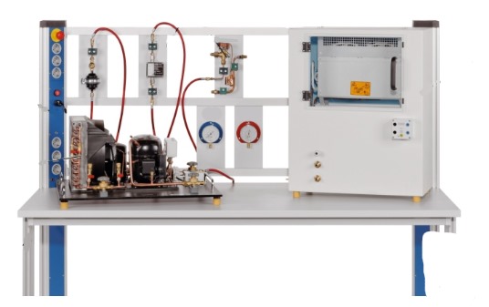
Refrigerator Model Training System
Order Code: 24258340.4
Category: General Lab Equipment V
Features: Refrigerator and Air Conditioning System Trainer The trainer is developed to meet the training requirements for comprehensive vocational ability, such as the air conditioner and refrigerator system pip...
SPECIFICATION
Features:
-
Refrigerator and Air Conditioning System Trainer
-
The trainer is developed to meet the training requirements for comprehensive vocational ability, such as the air conditioner and refrigerator system pipe line installation, electrical wiring, engineering commissioning, faults diagnosis etc.
-
With modular design, it mainly should consist of guide rail type aluminium alloy platform, air conditioning system, refrigerator system, electrical control system etc.
-
It is equipped with thermal protective device, it provide overheating and overload protection for compressor
-
Automatic tripping operation to cut off power supply when the leakage current exceeds a certain value
-
Safety protection: Overvoltage, overcurrent, overload, leakage protection, safety in accordance with related standards
Training Contents:
-
Pipeline design of air conditioning and refrigerator system (Cutting, bending, expanding, welding, etc.)
-
Install the pipeline into right location on air conditioning and refrigerator system
-
Accomplish the pressure maintaining, leak hunting of air conditioning and refrigerator system
-
Estimate the winding of compressor and accomplish the laying and connection of system circuit
-
Air conditioning and refrigerator system vacuumisation training
-
Air conditioning and refrigerator system refrigerating fluid filling training
-
Electrical debugging of air conditioning and refrigerator system
-
Working condition adjustment of air conditioning and refrigerator system
Technical Specifications:
Power supply and instrument module
-
Power input: AC 220V, with power indicator
-
Meter: AC voltmeter 0 ~ 250V, ammeter 0 ~ 5A
-
Power output: 220V, fuse 10A
-
Terminals: 4mm sockets 8pcs
-
Leakage protection: RCCB
-
Size: 245mm x 330mm
Air-conditioner electrical control module
-
emperature sensor: Indoor pipeline
-
Capacitor: Outdoor/indoor fan, compressor
-
Terminals: 4mm sockets 16pcs
-
Working indicator: Red, blue, yellow
-
Silk printing: Electrical schematic diagram
-
Others: Push button, 5A fuse, etc.
-
Size: 245mm x 330mm
Refrigerator electronic temperature control module
-
Simulated indicator: Pipeline/under heater, defrost heater
-
Refrigerating/freezing chamber temperature sensor
-
Rotary knob for temperature setting
-
Terminals: 4mm sockets 15pcs
-
Silk printing: Electrical schematic diagram
-
Size: 245mm x 330mm
Refrigerator intelligent temperature control module
-
Simulated indicator: Defrost heater, compressor, door lamp, air door, fan
-
Sensor: Refrigerating/freezing/varying temp chamber temperature sensor, refrigerating/varying temp chamber defrost sensor
-
Terminals: 4mm sockets 22pcs
-
Silk printing: Electrical schematic diagram
-
LCD display module with mode selection
-
Others: Toggle switch, 3A fuse, etc
-
Size: 245mm x 330mm
-
Input Voltage: Single-phase three-wire AC 220V ± 10%, 50Hz
-
Operating temperature: -10 ~ 40°C, below RH 85%
-
Overall power consumption: ≤1.5KVA
-
Dimension: 1500mm × 830mm × 1210mm (approx.)
-
Tools to be supplied: Portable welding torch, Rotary-vane vacuum pump, Pipe bender, Dual-gauge valve, Adapter, Monkey wrench, Tapeline, Charging hose, Socket head wrench, Expand tube reamer, Cutting-off tool, Monkey wrench and Chamfering tool
-
It is supplied with below Cloud Based Air Quality Monitoring System (AQMS) for Laboratory Environment Analysis:
Features:
-
It is a cloud-based air quality monitor that records and displays real time data for a wide range of parameters, such as particulate matter, pollutant gases, temperature, humidity, and barometric pressure
-
With active internet connection, user should be able to monitor this data live from computer or phone
-
The monitoring system is available with four fundamental sensors: particulate matter, temperature, relative humidity (RH), and barometric pressure (BMP)
-
Additionally, it is supplied with minimum four gas sensors
-
Configuration which is track indoor air quality by detecting PM2.5, PM10 and VOCs and identify harmful gases like Carbon Monoxide (CO), Carbon Dioxide (CO2), Nitrogen Oxide (NOx), and Volatile Organic Compounds (VOCs), enabling improvements in ventilation and air purification
-
It is meticulously designed to withstand extreme conditions, operate reliably in temperatures as low as -20 °C and humidity levels up to 99%
-
It is suitable for both indoor and outdoor environments Integrated Heater for maintaining stable temperature, melting snow, ensuring precise measurements.
-
It operate on both WiFi and 4G LTE networks for remote monitoring
-
For 4G LTE Network, SIM card is supplied by the bidder
-
Quick setup and intuitive cloud dashboard for easy monitoring
-
It is supplied with 32GB microSD card and cloud storage
-
Internal data backup during cloud connectivity interruptions
-
It save data to the SD card, even in offline
-
Cloud facility to be used for data access, system updates, and firmware tweaks
-
Warnings is displayed in cloud data for SD or cloud upload issues
-
Quick Deployment: Ready to roll right out of the box; This robust system must be delivered as primed for setup in under 15 minutes
-
Reliable Performance: Designed for resilience, it guarantee unwavering functionality in temperatures ranging from a chilly-20 to a scorching 50°C.
Technical Specifications:
-
Particulate Matter Measurements:
-
Range: 0 to 1000 µg/m3
-
Mass concentration measurements of PM1, PM2.5, PM4 and PM10
-
Measurement resolution: 1 µg/m3
-
Sensor lifetime: 10 years or higher
-
Mass concentration accuracy:
-
PM1 and PM2.5: - 5% (0 - 100 μg/m3) - 10% (100 - 1000 μg/m3)
-
PM4 and PM10: 25% (0 - 1000 μg/m3)
-
Startup time: <60s
-
Response time: <30s
-
Acoustic emissions level: 24 dBA at 0.2m
-
Long term acoustic emission level drift: +0.5 dB(A)/ year
Operating range
-
Temperature: -20 to 50°C
-
Relative humidity: 20 - 99% (non-condensing)
-
Barometric pressure: 300 - 1200 mbar
-
Temperature, relative humidity, and barometric pressure measurements:
Temperature
-
Measurement range: -40 to 85°C
-
Accuracy: Typical ±0.1°C (0 to 60°C), max. ±0.3°C (-40 to 85°C)
-
Resolution: 0.01°C
Relative humidity
-
Measurement range: 0 to 99% (non-condensing)
-
Accuracy: Typical ±1%; max. 2% (0 to 90%) and ±3% (91 to 100%)
-
Resolution: 0.01%
Barometric pressure
-
Measurement range: 300 to 1200 mbar (30 to 120 kPa)
-
Accuracy: ±1 mbar (0 to 65°C)
-
Resolution: 0.01mbar
-
Gas sensors should be included:
-
Volatile Organic Compound (VOC):
-
Sensor output: 0 - 500 VOC Index
-
Response time (τ63%): <10s
-
Device-to-device variation: <±15 VOC Index points
-
Repeatability: <±5 VOC Index points
-
Carbon Monoxide (CO):
-
Measurement range: 0 - 1000 ppm
-
Maximum overload: 1000 ppm
-
Accuracy: ≤ 2ppm
-
Response time: <30s
-
Repeatability: <1%
-
Lower detectable limit (LDL): ≤2ppm
-
Resolution: 0.1 ppm
-
Expected lifetime: >5 years in air
-
Cross sensitivity: Hydrogen (20 ppm in 100 ppm concentration)
-
Operating Temperature range: -40°C to 55°C
-
Operating Pressure range: 800 to 1200 hPA
-
Operating humidity range: 15 - 95%
-
Carbon Di-oxide (CO2):
-
Range: 400 - 5000 ppm
-
Accuracy:
-
± (50ppm + 2.5% of reading): 400 - 1000 ppm
-
± (50ppm + 3% of reading): 1001 - 2000ppm
-
± (40ppm + 5% of reading): 2001 - 5000ppm
-
-
Repeatability: ± 10ppm
-
Response time: 60s
-
Additional accuracy drift after five years: ± (5ppm + 0.5% of reading)
-
Formaldehyde (CH2O):
-
Measurement range: 0 - 5 ppm
-
Maximum overload: 10 ppm
-
Accuracy: ≤ 0.05 ppm
-
Response time: <120s
-
Repeatability: <1%
-
Lower detectable limit (LDL): ≤ 0.05ppm
-
Resolution: 0.01 ppm
-
Expected life time: >3 years in air
-
Long-Term Drift: <1% / month
-
Operating Temperature range: -20°C to 55°C
-
Operating Pressure range: 800 to 1200 hPA
-
Operating humidity range: 15 - 95%
-
Cross sensitivity: - Hydrogen Cyanide (<1ppm in 10ppm concentration) - Hydrogen (<3ppm in 100ppm concentration) - Sulfur Dioxide (<1ppm in 10ppm concentration)
-
Power supply and Enclosure:
-
Power supply: AC/DC adapter should be included
-
Weatherproof enclosure: Protection from rain and sunlight exposure
-
The enclosure should have Top cover, Status LED, Air inlet & outlet facility, Sensor probe connector, Power Jack connector etc.
The status LED blinking should interpret below conditions -
-
0 - Initialize device
-
1 - Normal Operation
-
2 - No internet connection
-
3 - Sensor error
-
4 - Internal backup storage is full
Software:
Connecting computer or phone
-
Activation of the device by powering it up.
-
Once the LED begins flashing establishment of a connection with a computer or phone will have to be initiated.
-
WiFi settings on computer or phone will have to be accessed and computer or phone will have to be connected using the password as mentioned in the operation manual - Upon successful connection, the system configuration panel will automatically launch in a browser window.
-
If the window does not appear automatically, user must Open a browser, enter 192.168.4.1 in the address bar and Press “Go” - Should click on the “Configure WiFi” function and choosing of WiFi network from the available WiFi networks list Configuration
-
Configuration of various settings for the device, such as the device name, user ID or email, time zone, logging interval, and running average for PM data can be done by clicking on Setup
-
Device name: The designated name to serve dual purpose: it should be employed in the cloud and also appear as the WiFi name when connecting a phone or desktop for configuration
-
Time zone: Selection of the suitable time zone and this setting to be used to record time data within the microSD card
-
Log Interval: This feature is allow users to choose their preferred logging interval, ranging from 15 seconds to 1 hour.
-
Available logging intervals is 15 sec, 30 sec, 1 min, 5 min, 10 min, 15 min, 30 min and 1 hour.
-
Running Average for PM Data: This configuration should determine whether the device is use a running average.
-
ON: The system is collect PM data every second. Upon logging the data, it is compute the average for the complete interval
-
OFF: In this scenario, the system is refrain from averaging the data throughout the entire interval.
-
Instead, it is calculate the average of the data from the last 5 seconds of the logging interval and record that specific value Sign in to Cloud
-
Navigation to Cloud Platform via address mentioned in the operation manual.
-
It come with the landing page that prompts end user for sign-in credentials.
-
Dashboard Overview: - After successfully signing in, end user must be directed to the dashboard of the Cloud Platform
-
The dashboard homepage is display a list of connected devices
-
Visible connected device is show details such as device name, model number, device ID, and subscription information
-
Additionally, there is an option to extend or purchase a subscription by clicking on the “Buy Subscription” button Data Summary
-
“Data Logger” tab in the top left corner should be available for the end user so that he/she can view the summary of data for a specific device from the list of connected devices on the cloud platform
-
After selecting the desired device, a summary of data is displayed on the screen which is show the minimum, maximum, and average values of the data stored in the cloud so far
-
Continue scrolling is find the graphical representation of data Live Monitoring
-
Live data monitoring is also be accessible directly from the dashboard by clicking on the available “LiveData” tab Editing Device and Finding Information
-
Minimum three icons is available
-
“i” symbol which must be designated for device information. Clicking on it is open a small window displaying device information.
-
End user is also receive the information of current firmware version.
-
Pen and paper sign icon which is designated for editing the device. From here, end user is able to modify logger name, set logging intervals, delete the logger, and erase data
-
Another icon is “download data” icon. Clicking on the download icon should appear a new window from where data downloading can be done by selecting the date and time.
-
Alternatively, data can be downloaded by selecting from the available time durations listed at the bottom of the data downloading window.
-
It is available in the name of “Quick Download”.
-
Data downloading from microSD card w/o removing
To do this, user must follow the following steps
-
Power off the device if it is currently powered on
-
Turn the power back on - From a computer or phone, search for available WiFi networks
-
Look for a network name that starts with the device name and connect to that network; If prompted, enter the password
-
The configuration page should automatically open - If not, open a browser and type 192.168.4.1 in the address bar
-
Click on the “Stored Data” button - If a microSD card is present, the files on the microSD card is displayed on the screen.
-
Download the files onto computer or phone using the browser
Accessories:
-
Probes and sensors as per configuration, Power adapter, Mounting bracket, Zip ties, Double sided foam tape, Screws, Micro SD card, Royal plugs, Printed operation manual etc.
Enquiry Form
Related Product

Tesca specialize in doing turnkey projects that is fully operable when it is handed over to the project authority. Starting from inception to application training, Tesca provides the services as ONE source solution. Working side by side with government authorities and people across the World, we help countries to perform better. We support countries grow their economies, strengthen their education and health systems and improve financial management. We do this by providing consultancy & training in environment safety, education, health strengthening.
Category
Useful Links
Contact Us
International Sales:
 91-9829132777
91-9413330765
India Sales:
91-9588842361
2025 © All Rights Reserved.