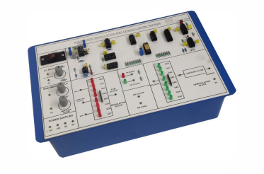
PCM, DPCM, CVSD Modulator & Demodulator
Order Code: 24257623.10
Category: General Lab Equipment V
It should have the following features: Should have onboard modulator and demodulator, DDS Signal Generator for standard and Arbitrary signals, Selectable sampling frequencies with respective line speed, On board Transmission effect, on board 2n...
SPECIFICATION
It should have the following features:
- Should have onboard modulator and demodulator, DDS Signal Generator for standard and Arbitrary signals, Selectable sampling frequencies with respective line speed, On board Transmission effect, on board 2nd order Butterworth Low Pass filter.
It should have the following Technical Specification:
- Instrument should support PCM, DPCM, CVSD modulation and demodulation technique.
- Internal Signal Generator: Direct Digital Synthesizer, Direct Digital Synthesizer Sine, Square, Triangle, Arbitrary signals.
- Frequency: 1500Hz, 1KHz, 2KHz, 3KHz.
- External Signal: Sine, Square, Triangle, Arbitrary signals, 3Vpp (Max.) input voltage, +1.5V DC offset, 500Hz to 3.5KHz Frequency.
- More than 40 SMD LED Indicators for DDS signal selection, DDS signal frequency selection, Sampling selection, Technique selection, Transmission Effect Attenuation (7dB & 10dB), Noise, Filter.
- 8MHz Crystal Frequency.
- Sampling frequency: 4KHz, 8KHz, 16KHz, 32KHz.
- Line Speed: 32KHz, 64KHz, 128KHz, 256KHz.
- Push switches for Selection Mode.
- More than 30 test points.
- Low pass filter: 5KHz cut-off frequency.
- 110V-260V AC, 50Hz power supply.
It should have the following experiments:
Study and analysis of:
- Predictor (Differentiator) output.
- DPCM modulated output.
- Parallel to Serial conversion by varying the line speed clock.
- Single bit DPCM output at different line speed clock.
- Serial to Parallel conversion.
- Differential Pulse Code Demodulation.
- Analyze the final DPCM demodulated output with Second order Low Pass Butterworth filter.
- CVSD Modulator & Demodulator:
- Continuous Modulation, Variable Slope Delta.
- Different step size generation at the given test points.
- Single bit PCM output.
- Continuous Demodulation, Variable Slope Delta.
- Analyze the final CVSD demodulated output with Second order Low Pass Butterworth filter.
- Transmission effects:
- Attenuator effect.
- Filter effect.
- Noise effect by varying the noise level.
Study and analysis of:
- Pulse Code Modulation:
- Sample & Hold output by varying the Sampling as well as signal frequency.
- Parallel to Serial conversion by varying the line speed clock.
- Single bit PCM output at different line speed clock.
- Pulse Code Demodulation:
- Serial to Parallel conversion.
- Analyze the final PCM demodulated output with Second Order Low Pass Butterworth filter.
- DPCM Modulator & Demodulator:
- Differential Pulse Code Modulation.
- Sample & Hold output by varying the Sampling as well as signal frequency.





 91-9829132777