Measurement of Magnetoresistance of Semiconductors
Order Code: 55532
Category: Physics Trainers
It is noticed that the resistance of the sample changes when the magnetic eld is turned on. The phenomenon, called magnetoresistance, is due to the fact that the drift velocity of all carriers is not same. With the magnetic eld on; the Ha...
SPECIFICATION
It is noticed that the resistance of the sample changes when the magnetic eld is turned on. The phenomenon, called magnetoresistance, is due to the fact that the drift velocity of all carriers is not same. With the magnetic eld on; the Hall voltage V=Eyt=|vx H| compensates exactly the Lorentz force for carriers with the average velocity; slower carriers will be over compensated and faster one under compensated, resulting in trajectories that are not along the applied eld. This results in an effective decrease of the mean free path and hence an increase in resistivity.
Here the above referred symbols are de nes as: v = drift velocity; E = applied electric eld; t = thickness of the crystal; H = Magnetic eld.
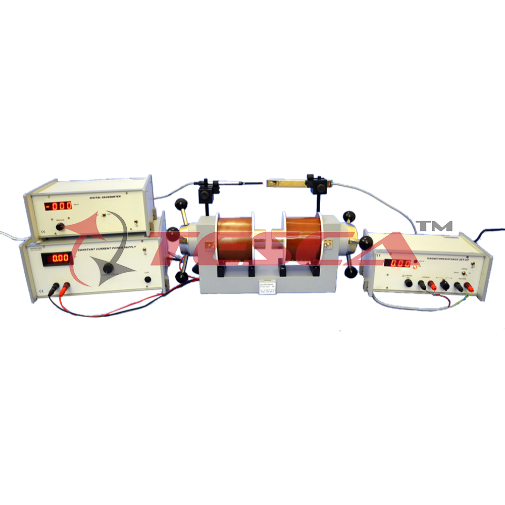
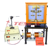
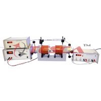
Experimentental Set-up for Magnetoresistance
The set-up consists of the following:
- Four probe arrangement
- Sample: (Ge: p-type)
- Magnetoresistance set-up
- Electromagnet
- Constant Current Power Supply
- Digital Gaussmeter
(1) Four Probe arrangement°
It consists of 4 collinear, equally spaced (2mm) and individually spring loaded probes mounted on a PCB strip. Two outer probes for supplying the constant current to the sample and two inner probes for measuring the voltage developed across these probes This eliminates the error due to contact resistance which is particularly serious in semiconductors A platform is also provided for placing the sample and mounting the Four Probes on It.
(2) Sample
Ge Crystal (n-type) dimensions: 10 x 10 x 0.5mm.
(3) Magnetoresistance Set-up
This unit consists of a digital millivoltmeter and constant current power supply The voltage and probe current can be read on the same digital panel meter through a selector switch.
(a) Digital Millivoltmeter
lntersil 3½ digit single chip ICL 7107 have been used. Since the use of internal reference causes the degradation in performance due to internal heating an external reference have been used. Digital voltmeter is much more convenient to use, because the input voltage of either polarity can be measured.
Specifications
Range : 0-200mV (100µV minimum)
Accuracy : ±0.1% of reading ± 1 digit
(b) Constant Current Power Supply
This power supply, specially designed for Hall Probe, provides 100% protection against crystal burn-out due to excessive current. The supply is a highly regulated and practically ripple free dc source.
Specifications
- Current : 0-20mA
- Resolution : 10µA
- Accuracy : ±0.2% of the reading ±1 digit
- Load regulated : 0.03% for 0 to full load
- Line regulation : 0.05% for 10% variation
The details of other sub-units can be had from their respective data-sheets.



 91-9829132777