Measurement of Magnetoresistance in Different Samples
Order Code: 55532A
Category: Physics Trainers
It is noticed that the resistance of the sample changes when the magnetic field is turned on. The phenomenon,called magnetoresistance, is due to the fact that the drift velocity of all carriers is not same. With the magnetic field on; the Hall voltag...
SPECIFICATION
It is noticed that the resistance of the sample changes when the magnetic field is turned on. The phenomenon,called magnetoresistance, is due to the fact that the drift velocity of all carriers is not same. With the magnetic field on; the Hall voltage V=Eyt=|v x H| compensates exactly the Lorentz force for carriers with the average velocity; slower carriers will be over compensated and faster one under compensated, resulting in trajectories that are not along the applied field. This results in an effective decrease of the mean free path and hence an increase in resistivity.
Here the above referred symbols are defines as: v = drift velocity; E = applied electric field; t = thickness of the crystal; H = Magnetic field.
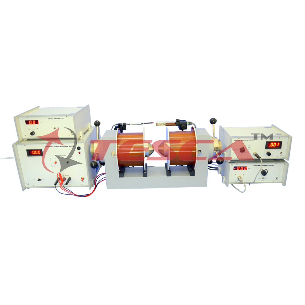
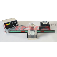
Experimentental Set-up for Magnetoresistance
The set-up consists of the following:
- Four probe arrangement
- Sample: (Ge: n-type)
- Constant Current Source
- Digital Microvoltmeter
- Electromagnet
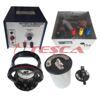
- Constant Current Power Supply
- Digital Gaussmeter
(1) Four Probe arrangement°
It consists of 4 collinear, equally spaced (2mm) and individually spring loaded probes mounted on a PCB strip. Two outer probes for supplying the constant current to the sample and two inner probes for measuring the voltage developed across these probes This eliminates the error due to contact resistance which is particularly serious in semiconductors A platform is also provided for placing the sample and mounting the Four Probes on It.
(2) Sample
Ge Crystal (n-type) dimensions: 10 x 10 x 0.5mm.
(Standard Sample included to enable the user to check the functioning of the setup)
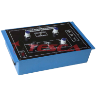
(3) Constant Current Source
(for low resistivity to medium resistivity samples)
It is an IC regulated current generator to provide a constant current to the outer probes irrespective of the changing resistance of the sample due to change in temperatures. The basic scheme is to use the feedback principle to limit the load current of the supply to preset maximum value. Variations in the current are achieved by a potentiometer included for that purpose. The supply is a highly regulated and practically ripples free d.c. source. The constant current source is suitable for the resistivity measurement of thin films of metals/ alloys and semiconductors like germanium.
Specifications
- Open Circuit Voltage : 10V
- Current Range : 0-20mA, 0-200mA
- Resolution : 10A
- Accuracy : 0.25% of the reading 1 digit
- Display : 3½ digit, 7 segment LED with autopolarity and decimal indication
- Load Regulation : 0.03% for 0 to full load
- Line Regulation : 0.05% for 10% changes
(4) D.C. Microvoltmeter
(5) Electromagnet
(6) Constant Current Power Supply
(7) Digital Gaussmeter
The experimental set-up is complete in all respect.




 91-9829132777