
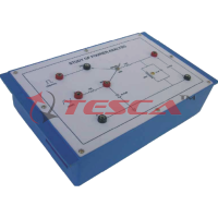
Measurement of Distortion of a R.F Signal Generator using distortion factor meter
Order Code: 36409
Category: Analog Electronics Trainers
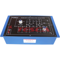
36409 Experimental Training Board has been designed specifically for the study of “Measurement of distortion of R.F. generator using Distortion Factor Meter”. It enables users to measure signal distortion across a range of frequencies. Us...
SPECIFICATION
36409 Experimental Training Board has been designed specifically for the study of “Measurement of distortion of R.F. generator using Distortion Factor Meter”. It enables users to measure signal distortion across a range of frequencies. Users can also introduce controlled distortion, this kit has great educative value for students, educators, and enthusiasts who wish to deepen their practical knowledge of RF signal analysis and measurement.
Object
To study measurement of distortion of a R.F. signal generator using Distortion factor meter.
Apparatus Description
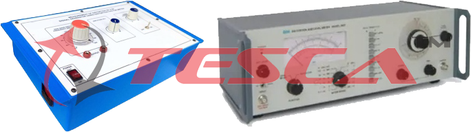
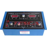
Distortion and Level Meter:
1. As Distortion Meter:
2 .as Level Meter:
- As Distortion Meter:
- Distortion Measurement: From 0.3% to 100% in six ranges of 0.3, 1, 3, 10, 30 & 100%.
- Frequency Range: 30Hz to 300 KHz fundamental frequency in eight ranges.
- Input Range: 0.3V to 10V
- Input Impedance: 600 ohms or 10K ohms (HI) unbalanced.
- Filter Characteristics: 30 Hz to 300 Hz better than ±0.6 dB, 300 Hz TO 3 KHz better than -0.8 dB, 3 KHz to 30 KHz better than -1 dB, 30 KHz to 100 KHz better than -2 dB, 100 KHz to 300 KHz better than -3 dB.
- Distortion Introduced: Less than 0.05%.
- Meter Indication: Proportional to average value of the wave-form.
- Frequency Dial Calibration Accuracy: Better than +3% of set frequency from 300Hz to 300KHz and better than +5% of set frequency from 30Hz to 300Hz.
- As Level Meter:
- Voltage Ranges: Full scale: 1, 3, 10, 30, 100, 300mV, 1, 3, 10, 30, 100 and 300V.
- Dbm Ranges: +50dBm to -60dBm in 12 ranges of 10dB steps.
- Frequency Range: 20Hz to 3MHz.
- Accuracy of Indication: Within 3% of f.s.d. at 10 Khz.
- Frequency Response: 1mV to 30 mV:
- ±0.3dB - 30Hz to 1.0 MHz
- ±0.5dB - 20Hz to 3.0 MHz
- 100 mV to 3 V:
- ±0.5 dB - 20Hz to 500 KHz
- ±1 dB - 20Hz to 3 MHZ
- 10 V & above ranges:
- ±0.5 dB up to 100 KHz (above 100 KHz not specified).
- Meter Calibration: The meter circuit is average reading type, calibrated in R.M.S. values for sinusoidal input.
- There are two linear voltage scales 0 to 3 and 0 to 10. The dB scale is calibrated from -20dB to +2dB.
- Input Impedance: About 10M ohms shunted by 40pF. Less than 10% change due to range switching.
- Residual Noise: Below -80dB.
- Output: Approx. 0.13V R.M.S. output for full scale deflection.
- Output Impedance: 2.2K ohms approx.
- Input Power Requirements: 230V AC ± 10%, 50Hz, single phase.
- Dimensions: 420W x 140H x 250D (mm)
- Weight: 4.2 Kgs. Approx.0
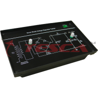
- R.F. Generator:
- Frequency Range: 20 KHz – 200 KHz.
- Voltage Range: 0- 2 V.
- Output Impedance: 600Ω
- Pot. Along with On-Off switch to create added distortion.
- Input Power Requirements: 230V AC ± 10%, 50Hz, single phase.
- Dimensions: W340 x H125 x D210 mm
- Weight: 1.2 Kgs. Approx.
Other Apparatus Required:
- Cathode ray oscilloscope 20MHz/Digital Storage Oscilloscope (D.S.O).
List of Accessories :
- B.N.C. to B.N.C. --------------------------------01
- B.N.C. to CROCODILE. -------------------------01
Enquiry Form
Related Product


Tesca specialize in doing turnkey projects that is fully operable when it is handed over to the project authority. Starting from inception to application training, Tesca provides the services as ONE source solution. Working side by side with government authorities and people across the World, we help countries to perform better. We support countries grow their economies, strengthen their education and health systems and improve financial management. We do this by providing consultancy & training in environment safety, education, health strengthening.
Category
Useful Links
Contact Us
International Sales:
 91-9829132777
91-9413330765
India Sales:
91-9588842361
2025 © All Rights Reserved.