Manual Isolation Valves

Order Code: LFC™_1B
Category: Range of Medium to High Pressure Valves
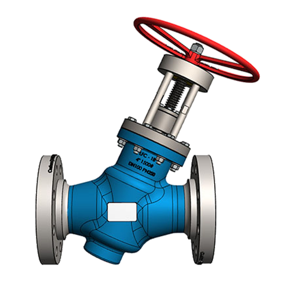
OVERVIEW The LFC_1B Manual isolation valve is manually operated via a handwheel and mechanical spindle arrangement. The spindle arrangement also functions as an indication mechanism, and based on the position of the spindle, it can be clearly seen...
SPECIFICATION
OVERVIEW
The LFC_1B Manual isolation valve is manually operated via a handwheel and mechanical spindle arrangement. The spindle arrangement also functions as an indication mechanism, and based on the position of the spindle, it can be clearly seen if the valve is in an open or closed position.
The Isolating valve ranges were designed to be energy efficient with a low flow co-efficient (Cv), simple and easy to operate.
LOW OPERATING TORQUE
The LFC™_1B manual isolation valve is hydrostatically balanced to enable easy opening and closing at any pressure and differential conditions. It does not require the use of a gearbox or a by-pass valve to balance pressure between the inlet and outlet. The differential pressures do not affect the operating torque which results in a relatively flat torque curve allowing for the fitment of smaller actuators.
CV VALUE & ENERGY EFFECIENCY (REDUCED OPERATING COSTS)
One of the primary costs after the initial capital outlay is running costs, especially in a pump station. A valve's Cv refers to the number of US gallons of water per minute at 60F that will flow through a valve with a pressure drop of one psi and is indirectly proportional to the amount of energy consumed to drive water through the valve. Cv should therefore be factored into the running cost of the system as it directly affects pumping cost and energy expense incurred to achieve the pumping volume require ments. Valves with better Cv values offer quantifiable energy savings over time.
OPERATING CONDITIONS
These valves are designed to operate in systems with relatively clean media like water or other liquids with a low percentage of suspended solids and chlorides. The valve's operating pH range is 2 - 14 pH.
SIMPLICITY
The LFC™_1B valve is designed to minimize wearing parts and in effect only has one moving part called the plug. The plug is a piston that is engineered to be balanced. The balanced plug uses the inline fluid pressure to remove the influence of differential pressure on operating torque. As such, the valve operating torque is the torque required to overcome the sum of the friction forces generated between the valve seals and the sleeve plus the weight of the plug (depending on the installation configuration). This torque requirement is not affected by inline pressure variants and as such makes the balanced valves extremely good for actuation applications as well as for isolation valves where manual operation is required. Removal of gearboxes reduces maintenance requirements and improves troubleshooting times.
LOW MAINTENANCE REQUIREMENT
All the moving parts of the LFC™_1B manual isolation valves are manufactured from stainless steel which increases reliability and durability. The LFC™_1B requires minimal maintenance, the majority of which, can be conducted with the valve remaining in situ.
The Manual isolation valve has an external bearing housing. The bearings can be greased via the installed grease nipple using a manual or automatic grease pump, while the valve is in service. Should the bearings get worn or damaged, they can be changed with the valve in an open position only, while the valve is in service.
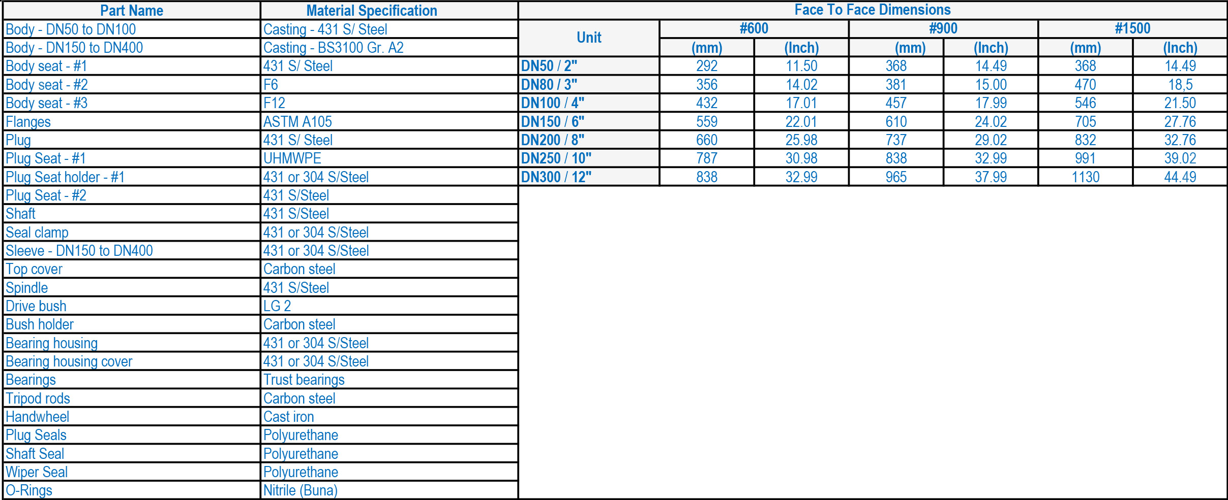
MATERIALS OF CONSTRUCTION & DIMENSIONS

FLOW RATES

DESIGN AND MANUFACTURING STANDARDS
The LFC™_1B manual isolation valve has been designed in accordance with various international standards as set out below:
ASME Boilers and pressure vessels design code
ANSI B16.10 ANSI B16.3
ANSI B16.34 ANSI B16.37
ANSI B16.5 ANSI N278.1
Available sizes: DN50 / 2" to DN400 / 16"
Pressure rating: up to 25MPa / 3 626 Psi
Face to face dimensions: ANSI B16.10 or other, minimum #600
Available end connections: ANSI B16.5, BS4504, BS10, AS/NZS 4331.1 (ISO 7005-1) DIN, All makes of grooved or ring joint couplings, HMP™ Coupling, HMP™-TE tapered couplings and other as per client’s requirement


 91-9829132777