Load Trainer Transformer Simulator
Order Code: 24257574.1
Category: General Lab Equipment V
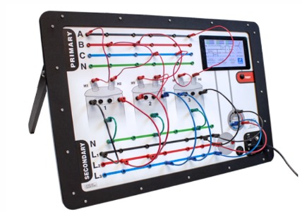
Specifications - The LOAD-TRAINER Transformer Simulator is a fully functional electrical trainer allowing simulation of most distribution transformer connection schemes. This device contains actual transformers that completely duplicate in-fie...
SPECIFICATION
Specifications -
The LOAD-TRAINER Transformer Simulator is a fully functional electrical trainer allowing simulation of most distribution transformer connection schemes. This device contains actual transformers that completely duplicate in-field situations.
The power unit’s components are not rated for continuous duty and may heat up during prolonged use. The power unit should not be on for extended periods of time and should only be on when taking voltage readings.
In addition to reduce the risk of electrical shocks, fire, etc.:
• Do not remove screws, covers or cabinet. Refer servicing to qualified personnel.
• Do not expose this device to rain, moisture or combustible materials.
• Select a place that is level, dry and between 41°F and 95°F. Do not place either unit on a heat generating object.
• Avoid a dusty place or a place subject to vibrations.
• The power cord supplied is configured and rated for standard 120 Volt, 10 Amp receptacles. It is to be used as a disconnect for this device by unplugging the power cord from the receptacle.
Includes :
1 Multiple-conductor cord with polarized plug (Green)
1 120 Volt, AC Power Cord (Black)
8 12” red ‘pin’ patch cords
3 12” black ‘pin’ patch cords
4 4” black ‘banana’ patch cords
5 12” red ‘banana’ patch cords
5 12” black ‘banana’ patch cords
Set-Up
The Load-Trainer requires two components to operate; the Front Panel (located in the large shipping case) and the Power Supply (located in the small shipping case). The Front Panel may be removed from its shipping case and set on a desk or table
using the built-in easel. The Power Supply remains in its shipping case and will be connected both to the Front Panel and to an electrical wall outlet. Check that the protective panel on the power supply is in place and the screws are securely fastened. This Power Supply case should be clear of all other items and lying flat on a level surface with the lid off for adequate ventilation. PLEASE NOTE - The 120 volts are REAL and NOT simulated. You must use caution whenever the unit is on. Never leave the unit on while unattended!
The unit should be on when measuring voltages and NEVER while removing or installing patch cords. Components could OVERHEAT if left on for extended periods a time!
1. Verify the “ON-OFF” switch on the Front Panel is in the “OFF” position.
1. Connect the green Multiple-conductor Cord to the Front Panel on the lower left hand corner. Turn the threaded collar on the plug clockwise a single turn to secure it to the polarized receptacle.
2. Attach the black Power Cord to the Power Supply using the female end. Plug in the Power Cord to a grounded AC outlet
Three Phase Power System
-
The four lines at the top of the Front Panel represent a three-phase four-wire power system (A, B, C, N).
-
The tip jacks located on the lines are connected to buss bars within the panel and are protected by fast acting thermal circuit breakers and disconnecting switches. The tip jacks are used to make connections from the three-phase four-wire power system supply to the primaries of single-phase transformers.
Indicator Lights
-
An indicator light is to the right of each three-phase power line at the top of the Front Panel.
-
This light will indicate when the line is energized.
Disconnecting Switches
-
Each three-phase power line has a toggle switch to the right of the indicator light on the Front Panel.
-
Power can be controlled to each line separately.
Circuit Breakers
-
Fast acting thermal circuit breakers are included on each of the three-phase power lines at the top of the Front Panel and function as fuses for accurate simulations.
-
Simply press the circuit breaker to reset.
Transformer Inputs
-
Three transformer outlines in the middle of the Front Panel use red input terminals (H1 and H2) which connect to actual transformers located behind the panel.
-
These connections are made using the PinPatch Cords (small metal ends). The plugs can be stacked, if desired.
Transformer Outputs
-
Each transformer has three black unlabeled output terminals.
-
They can be thought of as X1, X2 and X3 from right to left respectively, where X2 is neutral in a 120/240 Volt transformer.
Load Lines
-
The lines at the bottom of the Front Panel represent load lines (N, L1, L2, L3).
-
Connections between the transformer output terminals and the load lines are made using the Banana Patch Cords (large metal ends). These can be stacked if desired.
AC Meter
-
An AC meter is on the lower right of the Front Panel and is used to measure the transformer’s output.
-
Tip jacks utilize Banana Patch Cords connected through the load lines or directly to a transformer.







 91-9829132777