
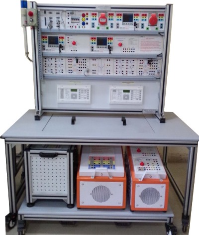
LECTRICAL POWER TRANSMISSION AND DISTRIBUTION WORKSTATION
Order Code: 24257358.2.58
Category: General Lab Equipment V
Three-phase transformers Transformer vector group. Transformer no load performance. Transformer short-circuit performance and equivalent circuit. Load performance. Zero impedance. Asymmetrical loa...
SPECIFICATION
Three-phase transformers
-
Transformer vector group.
-
Transformer no load performance.
-
Transformer short-circuit performance and equivalent circuit.
-
Load performance.
-
Zero impedance.
-
Asymmetrical load.
-
Autotransformer.
-
Parallel operation.
-
Transmission lines
Studies on three-phase transmission lines
-
No-load performance, Ferranti effect.
-
Matched load performance.
-
Three-phase symmetrical short-circuits.
-
Resistive-inductive load.
-
Resistive-capacitive load.
-
Zero-phase impedance.
-
Parallel compensation for a resistive-inductive load.
-
Series compensation for a resistive-inductive load.
-
Three-phase asymmetric short-circuit.
Parallel and series connection of transmission lines
-
Series connection of two lines.
-
Parallel connection of two lines.
Transmission line with earth-fault compensation
-
Earth fault on a line with an isolated star point.
-
Petersen suppression coil. Power distribution
Three-pole double busbar systems
-
Basic double busbar system.
-
Double busbar system with load.
-
Busbar coupling.
Network topologies
-
Radial network.
-
Meshed network.
The minimum set of power engineering modules shall include the following:
MOTORIZED THREE-PHASE POWER SUPPLY
-
Motorized three-phase variable power supply, power supply unit for variable 3-phase voltage suitable for supplying ac machines.
-
It must provide an AC output 3-phase from 0 to 400 V, 2 A minimum.
-
With a 16 A, 30 mA differential magneto-thermal main switch, a key operated emergency push-button, start and stop push buttons, a motor protection circuit breaker: 6.3 to 10 A.
-
Multifunctional digital instrument to voltage, current and power measurement on a single phase.
-
The analysed phase can be chosen by a selector located on the front panel.
-
Terminals for the external control of the motorized variator 4 mm safety terminals, RS485 port for Modbus communication"
"THREE-PHASE TRANSFORMER
-
Three-phase transformer for feeding a transmission line model 400 kV with scale factor 1:1000.
Primary
-
3 x 400V windings with tap at 230V
-
Star or delta connection
-
Protected with fuses on the rear Secondary
-
3 x 230V windings with taps at +5%, -5%, -10%, -15%
-
Star connection for 3 x 400V
-
Protected with fuses on the rear Tertiary
-
3 x 230 V
-
Delta connection Rated power: 1000 VA
-
Various star and delta connections possible with different vector groups with insulated front panel, 4 mm safety terminals.
THREE-PHASE POWER METER
-
Consist of a three-phase network monitoring device.
-
Insulated front panel and it must be suitable for the measurement of three-phase RMS, and peak values of voltages and currents (for 3 and 4 wire connections) as well as active, reactive, and apparent power, active, reactive, and apparent energy, power factor, THD and frequency.
-
It must have the following technical features:
-
Input voltage: nominal 400Vac (Three-phase: 80...690V, 50...400V per phase)"
-
"Input current: up to 10A (5A with 10:5 current transformers)
-
Operating frequency: 47…63 Hz
-
Auxiliary supply: 80…265 Vac 50/60Hz with single- phase from mains
-
On the front panel, 2 ports RS485 (Male/Female) supporting ModBus RTU protocol and allowing the module to be connected to high-level acquisition software, A power-on switch
-
LCD display features:
-
Number of reading points: 10 000, 4 digits, 8-digit counter, reading updates 1.1 second, Insulated front panel with 4 mm safety terminals
RESISTIVE LOAD
-
Consist of a single or three-phase resistive step-variable load.
-
Metallic box, on the front panel all the controls, the protections, the output terminals, and a schematic diagram on PVC label must be shown.
-
Composed by three resistances, with possibility of star, delta, and parallel connection, controlled by three switches with fuses protection.
-
As a function of the switch positions, there must be the following phase values: As a function of the minimum of 7 switch positions, with resistance range from 100 to 1000 ohm and max power per phase ranging from 400 to 40 watt Maximum power in single or three phase connection is 1200 W."
-
"Rated voltage in star connection 400 V, in Δ connection
-
230V, in single-phase 230V.
-
It must have insulated front panel, 4 mm safety terminals.
INDUCTIVE LOAD
-
It must consist of a single or three-phase inductive step- variable load. Housed in a metallic box.
-
Metallic box, on the front panel all the controls, the protections, the output terminals, and a schematic diagram on PVC label must be shown.
-
Composed by three inductances, with possibility of star, delta, and parallel connection, controlled by three switches with fuses protection.
-
Composed by three inductances, with possibility of star, delta, and parallel connection, controlled by three switches minimum of 7 switch positions, with inductance range from
-
0.5 to 5 H and max power per phase ranging from 30 to 300 VAR
-
Max reactive power 900 VAr in three-phase or single-phase connection.
-
Rated voltage in star connection 400V, in Δ connection is
-
230V, in single-phase 230V, 50Hz. Insulated front panel, 4 mm safety terminals.
CAPACITIVE LOAD
-
Consist of a single or three-phase capacitive step-variable load. Housed in a metallic box.
-
Composed of a rugged metal structure and on the front panel all the controls, the protections, the output terminals, and a clear synoptic diagram shall be collected.
-
This item must be provided also with fuses protection."
-
"Composed of capacitors, with possibility of star, delta, and parallel connection, controlled by three switches with fuses protection.
-
The load with star, delta, and parallel connection, controlled by three switches, minimum of 7 switch positions, with capacitance range from 1 to 20 microfarad and max power per phase ranging from 30 to 300 VAR
-
Max reactive power in single-phase or three-phase connection 900 VAr.
-
Rated voltage in star connection must be 400V, in Δ connection must be 230V, and in single-phase must be 230V/50 HZ.
-
4 mm safety terminals included on the front panel for the electrical connection.
POWER CIRCUIT BREAKER - - 4 units
-
Three-phase power circuit breaker with normally closed auxiliary contact. It must have insulated front panel with the electrical scheme.
Features:
-
Contact load capability: 400 Vac, 3 A
-
Supply voltage: single-phase from mains
Power circuit:
-
Insulation voltage: 750V
-
Thermal current: 20A
Auxiliary contact:
-
Insulation voltage: 750V.
-
Rated current: 3A
Auxiliary power:
-
Single-phase voltage 220V, 50-60Hz"
-
Push buttons “on” and “off” or externally via PLC or RELAY.
The state shall be indicated by leds:
-
Green led = open contacts
-
Red led = closed contacts
While at SIGNAL OUTPUT terminals will be available a TTL level:
-
Low level (0V) = open contacts
-
High level (5V) = closed contacts
The RS flip-flop state shall be indicated by a led:
-
Yellow led = set flip-flop
-
4 mm safety terminal and 2 mm terminals with protection fuses.
LINE CAPACITOR
-
Module with insulated panel, three-phase transmission line capacitor with exactly half of the operating capacitance of the 400 kV transmission line model with a length of 360 km, Capacitance:3 x 2.5 µF, 450 Vac.
-
Insulated front panel, 4 mm. safety terminals.
DIGITAL VECTOR GROUP METER
-
Allows to measure and compare the voltage value and phase angle between two different inputs to determine the transformation ratio and vector group of a three-phase transformer.
-
Both voltage values visualized at the same time on the LCD display, and a double digital bar graph makes it easy to compare them.
-
Communicate with the device through the RS485 serial port using Modbus protocol, to collect data using a supervision software such as SCADA.
Features:"
-
Automatic Scaling
-
Input range: 0 ÷750 Vac, 50/60Hz
-
Accuracy: +/- 0.5%
-
Resolution: 16bits
-
Refresh rate: 0.5s
-
Power supply: 90 ÷260 Vac, 50/60Hz
-
Power consumption: 3VA
-
Communication: Modbus (RS485) Insulated front panel, 4 mm. safety terminals.
-
The module must be supplied with manual in English language.
DIGITAL AC/DC MULTIRANGE POWER METER
-
Measure the power (P, Q, S) on a single circuit branch in AC and DC.
-
The RMS value of the voltage, current and active power (P) visualized on the LCD display along with the reactive (Q) and apparent power (S) values.
-
Communicate with the device through the RS485 serial port using Modbus protocol, to collect data using a supervision software such as SCADA
Technical features:
-
Automatic Scaling
-
Current range: 0 ÷ 20 Iac/dc, 50/60Hz
-
Voltage range: 0 ÷ 750 Vac/dc, 50/60Hz
-
Power range: 0 ÷ 1000W, VAr and VA
-
Accuracy: +/- 0.5%
-
Resolution: 16bits
-
Refresh rate: 0.5s
-
Power supply: 90 ÷ 260 Vac, 50/60Hz
-
Power consumption: 3 VA"
-
Communication: Modbus (RS485) Insulated front panel, 4 mm. safety terminals.
OVERHEAD LINE MODEL
Three-phase model of an overhead power transmission line features:
-
360 km long
-
Voltage: 400 kV
-
Current: 1000 A.
-
Scale factor - 1:1000
-
Line resistance: 13 Ω
-
Line inductance: 290 mH
-
Mutual capacitance: 0.5 μF
-
Earth capacitance: 1 μF
-
Earth resistance: 11 Ω
-
Earth inductance: 250 mH
-
Insulated front panel, 4 mm safety terminals.
LINE MODEL
Three-phase model of an overhead power transmission line features:
-
110 km long
-
Voltage: 400 kV
-
Current: 1000 A.
-
Scale factor - 1:1000
-
Line resistance: 3.3 Ω
-
Line inductance: 80 mH
-
Mutual capacitance: 100 nF
-
Earth capacitance: 200 nF
-
Earth resistance: 3 Ω
-
Earth inductance: 69 mH"
-
"Insulated front panel, 4 mm safety terminals. PETERSEN COIL
Module with insulated panel, Petersen coil, inductance with 20 taps for earth fault compensation in transmission lines:
-
2000mH-1800mH-1600mH-1400mH-1250mH-1100mH-
-
980mH-860mH-750mH-620mH-500mH-400mH-300mH-
-
220mH-160mH-120mH-80mH-40mH-20mH-5mH-0.
-
Inductance: 0.005 ... 2 H
-
Rated voltage: 230 V
-
Rated current: 0.5 A 4 mm. safety terminal
-
Insulated front panel with the electrical scheme. DOUBLE BUSBAR WITH TWO DISCONNECTORS - 3 units
-
Module with insulated panel.
-
Suitable for extending the double busbar system. Insulated front panel with the electrical scheme and four light push buttons (two red and two green).
-
Breaker switch using “on” and “off” push-buttons or externally via the switching contact PLC or RELAY. Contacts state shall be indicated by LEDs:
-
Green led = open contacts.
-
Red led = closed contacts.
-
While at SIGNAL OUTPUT terminals will be available a TTL level:
-
Low level (0V) = open contacts.
-
High level (5V) = closed contacts.
-
The RS flip-flop state shall be indicated by a led:"
-
Yellow led = set flip-flop.
-
4 mm. safety terminal and 2 mm. terminals included on the front panel for the electrical connection.
THREE-PHASE POWER SUPPLY
-
Suitable for a three-phase supply at the mains voltage and frequency.
-
Output: three-phase + N + T at safety terminals.
-
Protection through differential magneto-thermal switch and pilot lamp.
-
Key operated switch for the three-phase supply and pilot lamps for the three phases.
-
Insulated front panel, 4 mm. safety terminals.
MODBUS COMMUNICATION HUB AND LOAD CONTROLLER
-
Insulated front panel including:
-
One RS485 input and four RS485 outputs on Channel 1 (4 Wire) on the rear,
-
One RS485 input and four RS485 outputs on Channel 2 (2 Wire) on the rear,
-
Analog output 1: 0 ÷ 10V,
-
Analog output 2: 0 ÷ 10V,
-
Twelve relay outputs: 1NO/1NC each with 2 mm terminals,
-
One switch for power on/off and a socket for power supply connector.
SCADA SOFTWARE
-
Software for control and data acquisition that must permit the operations of control and data acquisition.
-
Personal computer supplied with the system"
"THREE-PHASE ISOLATION TRANSFORMER
-
Placed between the three-phase mains and the laboratories providing a three-phase secondary voltage with isolated neutral suitable for the modules operation.
Technical features:
-
Three-phase mains input with +10%/-10% adjustment.
-
Output: 400V with +5%/-5% adjustment. 3 x three phase CEE sockets (3P+N+E)
-
2 x single phase CEE sockets (2P+E) 2 x single phase type F socket
-
16 A, 30 mA differential magneto?thermal protection.
-
Motor-protection circuit breaker: 6.3 to 10 A.
-
Mushroom emergency stop push-button
-
Maximum output power: 6 KVA KIT OF CONNECTING LEADS HOLDER FOR LEADS
-
Realized in a rugged structure to store and organize the various connecting leads in the laboratory.
-
Equipped with wheels at the base.
THREE-LEVELS FRAME - 2 units
-
Metal frame with three levels for fitting the modules of the laboratory with a led strip on the top and a PC holder which is mounted on the workbench 120X90
WORKBENCH - 2 units
-
With melamine flatbed and two holes on the flatbed to allow the assembly of a three-level frame.
Technical features:
-
Complete with locking wheels"
-
"Supplied with 15 sockets protected by a thermal magnetic circuit breaker.
-
WORKBENCH (60cm * 90cm ) - 2 units Complete with locking wheels."
Enquiry Form
Related Product


Tesca specialize in doing turnkey projects that is fully operable when it is handed over to the project authority. Starting from inception to application training, Tesca provides the services as ONE source solution. Working side by side with government authorities and people across the World, we help countries to perform better. We support countries grow their economies, strengthen their education and health systems and improve financial management. We do this by providing consultancy & training in environment safety, education, health strengthening.
Category
Useful Links
Contact Us
International Sales:
 91-9829132777
91-9413330765
India Sales:
91-9588842361
2025 © All Rights Reserved.