Fuel Injection Trainer - Multi Point Efi System
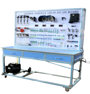
Order Code: 22235575.3.19
Category: General Lab Equipment I
The Four-Cylinder Engine trainer should consist of a complete, fully operational Multi Point EFI system. Original components should be utilized and clearly laid out on a display board that is mounted on an integrated floor stand, made from powde...
SPECIFICATION
The Four-Cylinder Engine trainer should consist of a complete, fully operational Multi Point EFI system. Original components should be utilized and clearly laid out on a display board that is mounted on an integrated floor stand, made from powder coated electro galvanized steel, mounted onto wheels for mobility. A color coded schematic chart, under a lexon polycarbonate protective screen, of the EFI system and circuit’s, should also be mounted onto the trainer for reference. The engine sensors have a signal generator to simulate various engine conditions and a corresponding electrical meter that continuously monitors the signal. The effect of altering the sensor condition should be immediately apparent on the meters. The Electrical wiring diagram is provided in a special design panel to incorporate Input/Output connections from sensors and ECU. ECU should be open source and programmable and have the ability to connect to a PC, for programming and displaying system data.
Specifications:
1. The following components should be included in Multi point EFI System Trainer:
A. Prime Components and Systems
- Electronic Control Unit (ECU)
- Test Point Panel for ECU Input/Outputs
- Fuel Tank Reservoir
- Electric Fuel Pump with pressure gauge
- Fuel Filter
- Fuel Distributor Rail with pressure gauge
- Fuel Injectors
- Fuel Pressure Regulator
- Graduated Fuel Volume Meter for each Injector
- Complete Ignition System (detailed below)
- Variable speed drive for ignition with Tachometer
- Silk screened engine Diagram showing layout of components
- Throttle position sensor
- Mass Air Flow Sensor
- Complete system sensors (detailed below)
- Sensor controls with meters (detailed below)
- Electrical relays and control devices
B. Sensors and Actuators
- Mass Air Flow Sensor or map sensor
- Intake Air Temperature sensor
- Throttle Position sensor
- Crank shaft Position and Engine Speed sensor
- Engine Temperature (coolant) sensor Lambda sensor
C. Ignition System
- Ignition Coil
- Ignition Distributor or Distributor less ignition
- Infinitely Variable Drive System for distributor
- Spark Plugs
- Set of High Tension Leads
D. System Controls and Devices
- Key Ignition switch with pilot lights
- System Relays
- Electronic Control Unit (ECU)
- Engine Speed Control
- Air Flow Control
- Throttle position Control
- Intake Air Temperature Control
- Engine Temperature (coolant) Control
- Lambda (Oxygen) Control
- Battery Voltage Control
E. Meters and Gauges
- Mass Air Flow meter
- Throttle Position meter
- Intake Air Temperature meter
- Engine (coolant) Temperature meter
- Engine Speed Tachometer (RPM)
- Lambda (Oxygen) meter
- Battery Voltage meter
- Fuel Pump pressure gauge
- Fuel Rail pressure gauge
F. 12 VDC Regulated Power Supply, 30 Amps
2. Accessories:
A set of 4mm terminals.
3. Included Accessories:
A. Electronic Fault Insertion System:
a. Multiple electronic fault insertion system: This
system should allow for 10 faults to be inserted at any one time. Faults can be inserted individually or in groups.
b. Electrical Circuit Diagram Panel with Test Points: Features electrical circuit diagram panel that incorporates
electrical test points that allow the student to take measurements during the troubleshooting exercises.
c. Electronic Fault Insertion System with LED Display: This should be incorporated into the electrical Circuit Diagram panel. The system should be able to activate the fault via
pushbuttons that in turn operate electrical relays that cause the fault to occur. When the fault is electronically activated a corresponding LED will illuminate
showing the fault is active.
d. Student Testing Mode: The LED fault indication
display can be deactivated, so that the faults can be active but the display is switched off.
e. Electronic Fault Reset Button:
The LED control should have a faultreset button that will
clear and reset the system back to normal. The trainer should come complete with a training course on the EFI fuel injection system operation and servicing including student job sheets and a technician manual.







 91-9829132777