Fiber Optic Communication Trainer
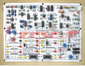
Order Code: 24258239.5
Category: General Lab Equipment V
All components must be visible on the top of the PCB. Circuit diagram must be given in the manual to trace the components on PCB. All Connecting functional blocks must be designed in a separate work area on the PCB to avoid damage of the ...
SPECIFICATION
- All components must be visible on the top of the PCB.
- Circuit diagram must be given in the manual to trace the components on PCB.
- All Connecting functional blocks must be designed in a separate work area on the PCB to avoid damage of the electronic components
- Transmitter should consist of two Siemens fiber optics LED each with wave-length of emission red visible (SFH756V) range from 600nm- 660nm and infrared (SFH450V) 900nm-950nm
- Receiver consist of two photo detector, PIN photo diode with responsivity of 0.3 µA (SFH250V)
- Photo Detector with TTL Logic output (SFH551V), Photo transistor with responsivity of 80µÁ / µW (SFH 350V)
- Photo detector with TTL logic output (SFH 551V)
- Pulse code modulation using CODEC chip
- Manchester coding / decoding
- Digital communication with pulse code modulation (PCM) using Motorola MC145502 CODEC chip
- Manchester coding / decoding technique
- Noise generator with White noise source output, Amplitude from 0 ~ 5Vpp
- PRBS generator with 16-bit switch selectable and Clock of 32 KHz, 64 KHz, 128 KHz
- Bit error rate measurement of10-bit counter with LED indication up to 255 count
- Time division multiplexing, 16 channels (64 Kbits/Sec),
- Two 8-bit user selectable markers in alternate frames
- 1.024 M Bits / Sec Data rate
- 2 channels voice PCM with telephone handsets (A Law)
- Plastic optical cable, step index, multimode
- Fiber length : 1 Meter, 3 Meter
- 6-8 Switch faults to be provided on board to study different effects on circuit
- 40-45 Test points to be provided on board to observe intermediate signals
- 2mm banana sockets Interconnections
- Power supply with GND, +5V, +12V, -12V
- Optical Fiber Patch Chords - 7 Nos
- Moulded 2mm Long connecting Links - 15 Nos
- Moulded Short connecting Links - 45 Nos
- Power Supply- 1 Nos
List of Experiments
- Setting Up Fiber Optic Analog Link
- Setting Up a Fiber Optic Digital Link
- Study of Losses in Optical Fiber
- Measurement of Numerical Aperture
- Study of Characteristics of Fiber Optic LEDs & Photo detector
- Study of Time Division Multiplexing
- Study Of 16-Channel Digital TDM Generation
- Study of Manchester Coding & Decoding
- Study of Time Division Demultiplexing
- Study of PCM Voice Coding And Codec Frequency Response
- Measurement of Bit Error Rate
- Study of Eye Pattern
- Pulse Broadeningin Fiber OpticCommunication






 91-9829132777