Excess Flow Shutdown Valves

Order Code: LFC™_1B
Category: Range of Medium to High Pressure Valves
OVERVIEW The LFC™_1B Excess flow shutdown valve is designed to shut down the flow of water in a piping system when an incident such as a pipe burst, or pipe break occurs. In most water piping systems, an instantaneous shutdown operation can ...
SPECIFICATION
OVERVIEW
The LFC™_1B Excess flow shutdown valve is designed to shut down the flow of water in a piping system when an incident such as a pipe burst, or pipe break occurs. In most water piping systems, an instantaneous shutdown operation can cause a water hammer that could result in serious damage to the piping system. In such a case, water will also continuously run out of the system until it is manually isolated for the problem to be attended to, and as a result a very high volume of water can get wasted. It is often not considered that the high volume of water wastage can substantially increase the cost of operating as well.
In such a case, the flow of water is required to be managed in a controlled manner by the use of a control valve that can gradually close off and reduce the flow of the water. Should there be a valve in the system that can automatically sense the pipe burst or break and shut down automatically such as the LFC™_1B Excess flow shutdown valve, the risks will be mitigated and the wastage of water can be controlled, which will eventually result in substantial cost savings.
The LFC™_1B Excess flow shutdown valve works on a very similar principal as a fuse in an electrical circuit, however, a fuse is designed to stop the flow of current instantaneously when the draw exceeds the maximum fuse rating, whereas the LFC™_1B Excess flow shutdown valve is designed to shut down in a gradual and controlled manner.
The valve is designed to execute this type of operation automatically, and it will start to close off when the desired set-flow (pre-set has been reached, thereby aiding in preventing a water hammer that could cause damage to the piping system from occurring.
The LFC™_1B Excess flow shutdown valve is designed to present a robust, simple and cost-effective solution to fluid handling issues in any industrial sector, off up to 25 MPa / 3 626 psi.
DESIGN FEATURES
At the core, the LFC™_1B range of Excess flow shutdown valves are designed with simplicity in mind. It has one only moving part called the plug assembly, which in effect minimizes the wear and tear of the valve, thereby increasing the valve’s overall life span.
The plug assembly is a piston that is engineered to be unbalanced, and uses the valve’s inline fluid pressure to control the differential pressures that influences it’s operating torque. As such, the valve’s operating torque induced by the plug assembly is all that is required to overcome the sum of all counter frictional forces generated by the valve’s seals, sleeve, cylinder, and the weight of the plug assembly (depending on the installation configuration).
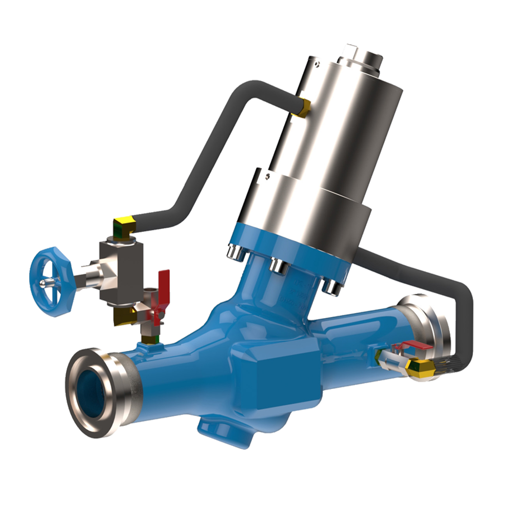
Under normal conditions, the downstream hydraulic pressure below the plug assembly keeps the valve in the open position via a primary hose arrangement. A secondary hose arrangement is used to feed a hydraulic pressure to the top of the plug assembly; however, the valve will remain open due to the reduced counteracting surface area on top of the plug assembly. The downstream pressure that keeps the valve open gets reduced with the help of the V-port assembly, and only when there is an actual instance of excess flow that takes place, the secondary hose arrangement that feeds the hydraulic pressure to the top of the plug assembly will start to exert a force that moves the plug assembly into the closed position.
As a safety feature, the LFC™_1B range of Excess flow shutdown valves are design to remain closed when it shuts down and cannot open by itself. When the hydraulic force from the downstream side of the valve that acts below the plug assembly starts to become greater than the hydraulic force from the upstream side of the valve that keeps it closed, only then will the plug assembly start moving to the open position once again.
Alternatively, a 3-way L-Port ball valve can be installed to manually override the excess flow shutdown valve. A qualified operator will be required to manually execute this operation, once the necessary maintenance has been done. When the valve is fully closed, it will remain closed and will not open by itself. The upstream pressure which causes the valve to remain closed can be released by simply opening the 3-way valve (changing the lever position) to vent the fluid that is contained in the valves closing chamber. By closing off the upstream pressure with the 3-way valve and venting the valve’s closing chamber, the valve will start to gradually reopen again in a controlled manner. The opening speed of the valve can be controlled with an external variable orifice (needle valve).
A bypass system designed to fill the piping system can also be installed to prevent water hammer and pipe shocking, especially in large bore piping systems. If a bypass system is used, the excess flow shutdown valve will only start opening when the downstream piping is close to reaching the fully charged line pressure. It is recommended to install an air release/vacuum break valve in the piping system after the excess flow shutdown valve, to release the air from the system while it is filling.
DEALING WITH CAVITATION
In most water reticulation and piping applications, most valves will always experience cavitation at the initial opening and final closing stages. The LFC™_1B Excess flow shutdown valve has been designed to reduce the effects of cavitation on the seating areas by the use of a specially designed V-port device which work in conjunction with the Plug assembly. The Images below shows various open positions of the LFC™_1B Excess flow shutdown valve’s V-port arrangement. This is shown at incremental percentages for illustration purposes.

Figure 1: 100% Open Position.
This illustration shows the Plug assembly in a 100% open position. Now, it can clearly be seen that the V-port is fully open, and the flow path is only slightly restricted. At this point, the flow is at its full demanded flow rate, and the V-port has little to no function. During a pipe burst or pipe break, the sightly restricted flow path will generate a pressure drop that is sufficient enough for the excess flow shutdown valve to sense a differential pressure and start shutting down. The flow direction is from inside the body seat and V-Port to the outside diameter of the V-Port.
Figure 2: 75% Open Position.
This illustration shows the Plug assembly in a 75% open position. It can clearly be seen that the V-port is almost fully open, and the flow path is still slightly reduced. After a pipe burst or break has occurred, the LFC™_1B Excess flow shutdown valve will start to close off in a controlled manner and reduce the flow in a linear pattern as it closes.
Figure 3: 50% Open Position.
This illustration shows the Plug assembly in a 50% open position. It can clearly be seen that the V-port is nearly half open, while the flow path is still reduced.
Figure 4: 30% Open Position.
This illustration shows the Plug assembly in a 30% open position. It can clearly be seen that the V-port creates a smaller orifice area, and the flow path is getting reduced. From this point, cavitation needs to be dealt with to increase the life expectancy of the valve. The V-port trim ensures that the seating elements are further apart from each other during a low flow condition, which allows cavitation to take place on the non-critical components of the valve.
Figure 5: 15% Open Position.
This illustration shows the Plug assembly in a 15% open position. It can be observed that the opening is proportionally reduced as the V-port opening becomes smaller at this point, the top of the V-port is exposed to a reduced flow path. This reduces cavitation at the low flow conditions.
Figure 6: 5% Open Position.
This illustration shows the Plug assembly in a 5% open position. It can be seen that the opening at the top of the V-Port just slightly exposed and is very small. This reduces cavitation at low flow conditions.
Figure 7: Closed Position.
This illustration shows the Plug assembly completely seated against the valve body, in a fully closed position. This indicates that the valve is fully closed.
OPERATING METHOD
The LFC™_1B range of Excess flow shutdown valves are hydrostatically operated and does not require any external equipment such as sensing devices, controllers, actuators, or electrical connections to operate. It can be installed in remote places where there is no access to electricity.
OPERATING CONDITIONS
The LFC™_1B range of valves are designed to operate in systems with relatively clean mediums like water, or other liquids with a low percentage of suspended solids and chlorides. The valve's operating pH range is between 2 - 14 ph.
VALVE SIZING
Please consult with a technical expert at Hydromine Projects International for clarification on correct valve sizing on your specific requirements.
MAINTENANCE REQUIREMENTS
The LFC™_1B range of valves require minimal maintenance, the majority of which can be conducted with the valve remaining in situ. All moving parts of LFC™_1B Excess flow shutdown valve is manufactured from stainless steel which increases their reliability and durability.
FLOW RATES

DIMENSIONS

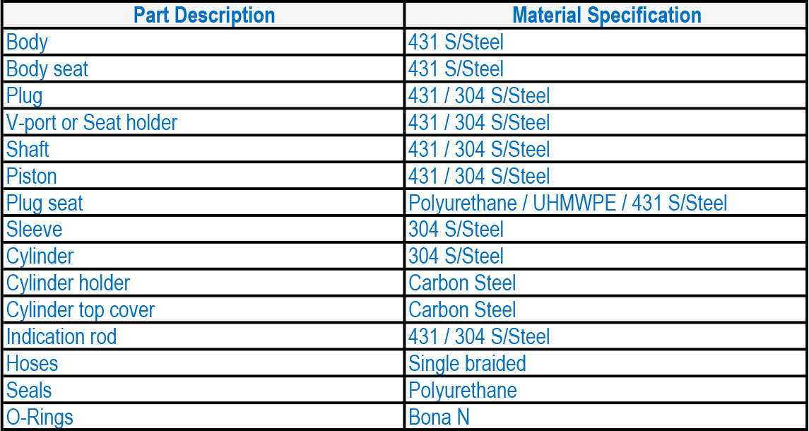
MATERIAL SPECIFICATIONS

DESIGN STANDARDS
The LFC™_1B Excess flow shutdown valve is designed in accordance with various International Boiler and Pressure vessel standards, as set out below:
ASME Boilers and pressure vessels design code
ANSI B16.10 ANSI B16.3
ANSI B16.34 ANSI B16.37
ANSI B16.5 ANSI N278 .1
Available sizes: DN50 / 2" to DN400 / 16"
Face to face dimensions to ANSI B16.10
Pressure rating: up to 25MPa / 3 626 psi
Available end connections: ANSI B16.5, BS4504, BS10, AS/NZS 4331.1
(ISO 7005-1) DIN, all makes of grooved or ring joint couplings, and various other types, as per client requirements.


 91-9829132777