
Electrical connection of refrigerant compressors
Order Code: 24258098.69
Category: General Lab Equipment V
Electrical connection of refrigerant compressors Use of a real refrigerant compressor Features correct electrical connection of a refrigerant compressor use of a real refrigerant compressor design and investigation of a safety chain ...
SPECIFICATION
Electrical connection of refrigerant compressors
Use of a real refrigerant compressor
Features
- correct electrical connection of a refrigerant compressor
- use of a real refrigerant compressor
- design and investigation of a safety chain
Specification
- experimental unit from the practical series for the training of mechatronics engineers for refrigeration
- correct electrical connection of a refrigerant compressor
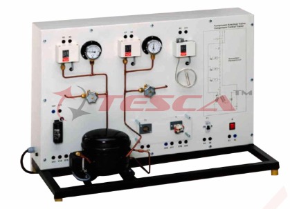
- refrigerant circuit with compressor, receiver, 2 valves and 2 manometers to investigate pressure switches on the delivery and intake sides
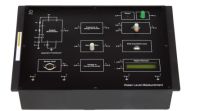
- electrical components for the start and operation of the compressor mounted clearly visible
- lab jacks and cables to connect the electrical components
- operation of a thermostat
- circuit diagram on the front panel for easy identification of the components
- refrigerant R513A, GWP: 631
Technical data
Refrigerant compressor
- power consumption: approx. 193W at 5/55°C
- refrigeration capacity: 374W at 5/55°C
Receiver: 0,8L
Manometer measuring ranges
- delivery side: -1...24bar
- intake side: -1...9bar
Pressure switch control range
- delivery side: 8...32bar
- intake side: -0,9...7bar
Thermostat: -5...35°C
Electrical components for the compressor
- start-up capacitor
- start-up relay
- overheat protection (bimetallic)
- automatic fuse
Refrigerant
- R513A
- GWP: 631
- filling volume: 300g
- CO2-equivalent: 0,2t , 230V, 50Hz, 1 phase
Electrical faults in refrigerant compressors nvestigation of important electrical components from refrigeration
Features
- real refrigerant compressor from practice
- investigation of important electrical components from refrigeration
- simulation of 15 faults
- Learning objectives/experiments
- electrical connection of refrigerant compressors
- read and understand electrical circuit diagrams
- design and operation of the electrical components of a refrigerant compressor
- o start-up capacitor
- o start-up relay
- o operating capacitor
- o overheat protection
- o main contactor
- o automatic fuse
- fault finding in electrical components
- o in idle state
- o under mains voltage
Specification
- experimental unit from the practical series for the training of mechatronics engineers for refrigeration
- investigation of the electrical components for the operation of a refrigerant compressor
- real refrigerant compressor from practice
- electrical components for the start and operation of the compressor arranged in the transparent switch cabinet
- general safety devices mounted clearly visible
- circuit diagram depicted on the front panel
- identification of 15 faults: multimeter measures voltages or resistances at the lab jacks
- refrigerant R449A, GWP: 1397
Technical data
Refrigerant compressor
- power consumption: approx. 870W Electrical components for the compressor
- start-up capacitor
- start-up relay
- operating capacitor
- overheat protection (bimetallic)
General safety devices
- main contactor
- automatic fuse
Refrigerant
- R449A
- GWP: 1397
- filling volume: 80g
- CO2-equivalent: 0,1t , 230V, 50Hz, 1 phase
Enquiry Form
Related Product


Tesca specialize in doing turnkey projects that is fully operable when it is handed over to the project authority. Starting from inception to application training, Tesca provides the services as ONE source solution. Working side by side with government authorities and people across the World, we help countries to perform better. We support countries grow their economies, strengthen their education and health systems and improve financial management. We do this by providing consultancy & training in environment safety, education, health strengthening.
Category
Useful Links
Contact Us
International Sales:
 91-9829132777
91-9413330765
India Sales:
91-9588842361
2025 © All Rights Reserved.