Dissectible Machines Trainer
Order Code: 46986
Category: Electrical Machine Lab
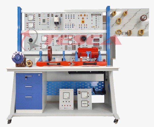
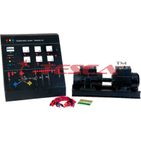
The 46986 Dissectible Machines System components form a complete trainer that covers a wide range of generators and motors - D.C., Single and Three Phase A.C. and Stepper. The trainer is built around the unique Dissectible Machine, which is designed ...
SPECIFICATION
The 46986 Dissectible Machines System components form a complete trainer that covers a wide range of generators and motors - D.C., Single and Three Phase A.C. and Stepper. The trainer is built around the unique Dissectible Machine, which is designed to introduce students to the principles of electrical motors and generators.
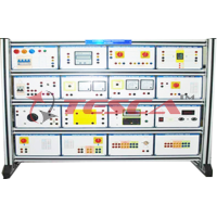
The trainer includes power supplies, drives and control equipment, loading and instrumentation modules that are all provided in the form of panels. These panels can easily be slotted in and out of a purpose-designed, bench-standing frame. The frame is constructed from an advanced, fibre-loaded, rigid plastic material which is electrically insulated for safety.
The trainer provides a dynamic approach to understanding electrical machine principles and construction covering a wide range of student levels from vocational to graduate Engineer. The Dissectible Machine has been designed so that the characteristics of the machines that can be assembled closely represent those of their industrial equivalents.
Curriculum Coverage
The unique Dissectible Machine System enables students to construct and investigate over fifty different machine assembly.
The System may be used to study a wide range of topics, from the principles of magnetic circuits and electrical machine theory through to 3-phase synchronous machines. Students are able to see clearly the component parts of the machine and how they are interconnected, both electrically and mechanically. They may assemble machines from these component parts and then investigate the operation and characteristics of them.
Electrical Machine Constituent Parts
Electromagnetic principles Elementary machine principles D.C. motors and generators Series, shunt and compound types A.C. single and three phase motor and generators Series, universal, single phase capacitor, split phase and repulsion motor Synchronous motors and generators single and three phase Split field, shaded pole and stepper motors Electrical Machines faults
System Components
- Baseplate
- Frame Ring
- Shaft Coupling Fixed & removable
- bearing housings
- Wound Stator
- Squirrel Cage Rotor
- Hand Crank Centrifugal Switch
- Brush holders & brushes
- Commutator/Slip Rings
- Interpoles
- Armature Poles & Hub
- Field poles
- Armature, Field & Interpole coils
- Compound Field Coils
- Tools and Hardware
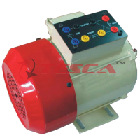
The focus of this system is a fully dissectible experimental machines kit. This allows over fifty machine assemblies to be built covering a wide range of A.C. and D.C., Single and 3-Phase motor and generator assemblies. The machines that may be assembled use low voltages, have protected rotating parts and operate at relatively low power levels, minimising the risk of accidents.
Nominal operating voltages are 50 V D.C. and 125 V A.C.
The separate field poles, Interpoles, armature poles, hub, 12-slot stator and squirrel cage rotor are made from electrical steel laminations riveted together. The coils are wound from synthetic enamel-covered copper wire and wrapped with a strong cloth-base tape. Each has 'coil finish' and identification bands. A stainless steel shaft of high corrosion resistance is supported by plain and self-aligning ball race bearings. These are held in aluminium alloy housings fixed to a cast aluminium baseplate. The shaft speed can range from very low values up to 3,600 rev/min (A.C. machines), or 5,000 rev/min (D.C. machines) according to the application. The Commutator, slip rings and brush gear are of simple design to facilitate armature assembly and give good accessibility. A sturdy component storage panel is provided for easy inventory control.
The following studies and machines assemblies may be investigated:
- Single phase A.C. induction motor, squirrel cage, 2 pole and 4 pole
- Single phase A.C. series universal motor
- Single phase A.C. repulsion motor
- Single phase A.C. synchronous motor/generator, 2 pole and 4 pole
- Single phase A.C. generator, rotating field
- Single phase A.C. generator, rotating armature
- 3-phase ac induction motor, squirrel cage, 2 pole and 4 pole
- 3-phase ac synchronous motor, 2 pole
- 3-phase ac synchronous generator, 2 pole
- A.C. brushless generator
- Stepper motors
- Shaded pole induction motor
- Split field series motor
- Dynamic braking of a D.C. motor
- Power factor correction of A.C. motors
- Synchronisation
- Synchronous motor characteristics
- Pole-changing induction motor
- D.C. shunt motor faults
- 4 pole induction motor faut
- Introduction to electromagnetism
- Machine operating principles
- Elementary A.C. and D.C. generators
- Machines with and without interpoles:
- D.C. series motor
- D.C. compound motor
- D.C. shunt motor
- D.C. shunt generator
- D.C. series generator
- D.C. compound generator
- D.C. separately excited generator
Variable Speed Drive
A D.C. variable speed drive is provided. It consists of a 250 W motor mounted on a base unit and an electronic motor drive providing the motor supply. The shaft speed range is from zero to 4,000 rev/min and all controls and fuses are accessible externally. It has current limiting, electronic control for good regulation and soft-start.
Measuring equipment A combination of electronic and more conventional analogue metering is provided to enable a full range of D.C. and A.C. parameters to be measured. The electronic single and three-phase measurements panel gives a digital read-out of such parameters as voltage, current, power, kVA, KVAR, KWH, etc. Large-scale analogue voltmeters and ammeters are provided for A.C. and D.C. readings together with a frequency meter and synchronizing lamps. A hand-held tachometer allows machine speed to be determined. Torque is measured by a friction brake mounted on the machine base. Both are supplied in the package.
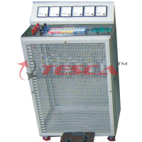
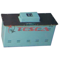
Loading Equipment Both electrical and mechanical loading devices are provided in the system. The electrical loading is carried out with variable resistance loads and a resistor/capacitor unit for A.C. single phase and three phase machines. The mechanical loading is by a friction (Mechanical belt) brake, which is calibrated for quantitive measurement.
Dissectible Machines System
- The full system comprises:
- Universal power supply
- Variable A.C./D.C. supply 5 A
- Dissectible machine components -
- Dissectible machines tutor
- Control switches and
- Resistor capacitor load unit
- Variable speed drive
- Variable resistance 200 Ohm 3 A
- Friction (Prony) brake
- Electronic single and three-phase measurements
- D.C. Voltmeter and ammeter x 2
- D.C. Milli ammeter centre zero
- Rectifier voltmeter/ammeter
- Synchronizing lamps
- A.C. voltmeter and frequency meter
- Digital optical/contact tachometer
- Patch leads
- Dissectible machines storage system
- System frame




 91-9829132777