
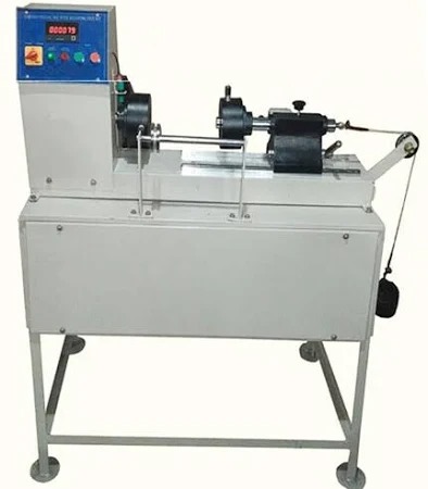
Digital Torsion Testing Machine
Order Code: 24258340.9
Category: General Lab Equipment V
Technical Features and Parameters: Torsion testing kit which should demonstrate the torsion in circular section specimens of different materials and lengths Flexible and modular with sensible size parts - should fit onto t...
SPECIFICATION
Technical Features and Parameters:
-
Torsion testing kit which should demonstrate the torsion in circular section specimens of different materials and lengths
-
Flexible and modular with sensible size parts - should fit onto the work panel for experiments and simple classroom demonstrations
-
Should be supplied in a hard-wearing storage tray with moulded insert to hold parts securely and a graphical list to help check the kit contents
-
Rugged and durable parts for safe ‘hands-on’ experiments - allowing better understanding
-
Should contain all parts needed for experiments showing the torsion in circular section specimens of different material and length
-
This kit should include different circular section specimens and adjustable chucks for experiments in torsion
-
Students to fix the specimens in the chucks and apply weights to a lever arm
-
The arm should apply a moment (torque) to one end of the specimen
-
A scale on the arm to show the angle of twist
-
Standard tests must show the relationship between torsion and ‘J’ (polar second moment of area) value
-
The choice of different specimens should allow comparisons of different specimen material and how it affects torsion, introducing the modulus of rigidity
-
Students should also be able to move the chuck positions for easy experiments showing the relationship between specimen length and angle of twist Experiments to be Performed:
-
Specimen length and angle of twist
-
Specimen material and angle of twist (modulus of rigidity)
-
Specimen ‘J’ value and angle of twist
-
Main parts: Choice of specimens, rotating & fixed chucks, dial caliper, rule, weight hangers & weights and hexagon tool
Work Panel:
-
Perfect size for experiments & should fit on any standard desk or bench top
-
Should be supplied with digital copy of all teaching material needed for the full Engineering Science range
-
Users should be able to fit the parts of their kit to the Work Panel to study or demonstrate an engineering science topic
-
Stable and multi-positional - to be used in many different ways to suit the experiments or demonstrations
-
Solid, thick perforated metal plate for long life and choice of fixing positions for the experiments
-
Simple thumbscrews for safe, quick and easy assembly
-
Assembled size in Portrait: 550 mm high x 380 mm wide and 280 front to back (approx.) or higher
-
Assembled size in Landscape: 450 mm high x 480 mm wide and 280 front to back (approx.) or higher
-
Should be supplied with below system to test torsion, tension and bending to illustrate how resistance strain gauges work and methods of measuring strains:
Features:
-
Benchtop bending system to test tension, torsion and bending to illustrate how resistance strain gauges work and methods of measuring strains in different structures
-
To be used to demonstrate Young’s modulus and Poisson’s ratio
-
Should be a compact benchtop or desktop type Strain Gauge Trainer
-
It should contain everything needed to show students how resistance strain gauges work on three different structures
-
It should be ideal for groups of two or more students to do experiments and for classroom demonstrations
-
Students should be able to use the small set of masses to load the bending and torsion systems, and the large set of masses to load the tension system
-
They should be able to use theory and known dimensions to calculate the stresses and strains and compare them with the strains measured by the strain gauges
-
Students should also connect and compare the performance of quarter, half and full-bridge strain gauge connections for each structure
-
The bending system should use gauges to measure direct tensile and compression strain
-
The torsion system should show the use of shear/torque strain gauges
-
The tension system should show the use of two gauges at right angles in a ‘Tee’ rosette
-
The strain display should include a set of high-accuracy dummy strain gauge resistors (plugs) and controls
-
These should allow the student to connect the strain gauges on the structures as quarter, half or full-bridge networks
-
The strain display should work with and give correct readings for all bridge connections and different gauge factors
-
An extra setting on the strain display should work with the tension system to prove Poisson’s ratio The strain display should have a socket for connection to Versatile Data Acquisition System
-
The trainer should show students different types of strain gauges
-
A clear, hard-wearing coating should protect each gauge from accidental damage and the environment
-
Should have enlarged mimic diagrams on the back plate of the trainer to show students what each gauge looks like, how it connects and how it fits on each structure
Learning Outcomes:
-
Introduction to the equipment and the different bridge connections (quarter, half and full-bridge)
-
Strains and stresses in a bending system
-
Strains and stresses in a torsion system
-
Strains and stresses in a tension system, Poisson’s ratio and Young’s modulus
-
Comparison of different strain measurement systems and how they could measure force
Technical Parameters:
Strain systems:
-
Bending system: - Minimum four standard gauges fitted to a given datum on a steel beam,
-
fixed as a cantilever - Nominal beam cross-section should be 5 mm x 20 mm
-
Torsion system: - Minimum two sets of identical 45-degree shear/torque strain gauge rosettes
-
fitted to a torsion bar - Nominal bar diameter should be 10 mm, torque arm length of 150 mm
-
Tension system: - Minimum two sets of identical 90-degree ‘Tee’ strain gauge rosettes fitted to
-
a tensile test specimen - Steel specimen should be supplied as standard - Nominal tension specimen cross-section should be 2 mm x 10 mm
-
Sets of masses: - Large mass set should give weights from 0.5 kg to 10 kg in a range of units - The small mass set should give weights from 10g to 500g in 10g units
-
Dummy resistors: - Set of minimum three plugs fitted with high accuracy resistors that matchthe strain gauges - Dummy plugs: 350? high precision resistors
Strain display:
-
Multiline display that should show: - Bridge output voltage (micro-volt) - Strain reading in micro-strain (me) - Active arms (gauges), Gauge factor - Should have VDAS output and Zeor button facility
-
Connections: - Quarter bridge - 01 gauge - Half bridge - 02 gauges - Full bridge - 04 gauges
-
Fixed bridge voltage: 5 VDC
-
Gauge factor range: 1.9 to 2.3
-
Configuration settings (Active arms): 1, 2, 4 and N (N = 2.6)
-
Power supply: 220 ~ 230V AC, 50Hz, 1 Phase
-
Versatile Data Acquisition System and Software:
-
Should be of bench mounted type
-
High-capacity, accurate, efficient and user-friendly automatic data acquisition hardware and software
-
Intuitive and easy-to-use software, with clear, customizable display and layout options
-
Recording data manually or automatically
-
Data capture set by time or intervals
-
Display of real-time data, in digital form or as an analogue meter
-
Real-time traces of analogue signals
-
Logging data for printing and later analysis
-
Exporting data for use by other software
-
Performing real-time calculations to generate user defined data Creating & printing charts and data tables
-
Computer connection: USB (Cable should be supplied)
-
Digital inputs: 6 off RJ45 connection & 4 off SPC (DTI) inputs
-
Analogue inputs: 1 DIN type socket for dual trigger input, 2 DIN type sockets for signal inputs of 0 to 10 V or 4 to 20 mA, Sample rate up to 25 kHz with 12 bit resolution, Bandwidth/ Filter cut-off 3 kHz (nominal)
-
Data export: XLSX file
Accessories to be supplied:
-
All mains connectors & cables and STP cables for equipment connection
-
Power supply: 220 ~ 230V AC, 50Hz, 1 Phase
Enquiry Form
Related Product


Tesca specialize in doing turnkey projects that is fully operable when it is handed over to the project authority. Starting from inception to application training, Tesca provides the services as ONE source solution. Working side by side with government authorities and people across the World, we help countries to perform better. We support countries grow their economies, strengthen their education and health systems and improve financial management. We do this by providing consultancy & training in environment safety, education, health strengthening.
Category
Useful Links
Contact Us
International Sales:
 91-9829132777
91-9413330765
India Sales:
91-9588842361
2025 © All Rights Reserved.