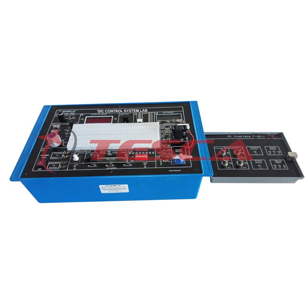
DIC Control System Lab explores students & industry professional to the fundamentals of digital imaging correlation Control System. It demonstrates, how one device can be used to manage, command, direct or regulate the behavior of other system. Sequential Control, Linear Control is also well explained in the trainer.
DIC Control System Lab has sensors like Vibration, Thermal imaging, Temperature sensor, Light sensor, DC motor, Filament lamps, IR sensor and many more which can be used for the study of Control system. There is a wide range of experiments which can be performed on the trainer. Application software for Interfacing with PC increases range of experiments.
Features:
01. FEA Validation
02. Temperature Control
03. Feedback concept
04. On board DC supply
05. Open loop Control system
06. DC motor control
07. Speed control
08. Close loop Control system
09. Servo motor control
10. Light intensity control
11. V/F & F/V conversion
12. LED bar display
13. Bread board for circuit design
14. User can design & develop own circuits
15. PC interface for open loop & Close loop control
16. PC based Frequency counter
17. PC based DC voltmeter
18. Real time graphical representation
19. User friendly software
20. Exhaustive course material & references
Technical Specifications:
DC Motor : 12 VDC
Servo Motor : 5 VDC
Temperature Sensor : 10 mV / ° C
Light Sensor : Photo Conductive Cell (LDR)
Light Source : Two numbers of filament lamps
V/F : For 0 - 5 V output is 0 -50 KHz (approx.)
F/V : For 0 - 50 KHz output is 0 - 5V (approx)
PC based Analog Inputs : 4 Inputs with 0 to 5 V / 0 to 10 V
PC based Analog Output : 1 Output with 0 to 5 V / 0 to 10 V
PC based Digital Inputs : 3 Inputs
PC based Digital Outputs: 3 Outputs
PC based DC Voltmeter : 0 to 10 V range
PC based Frequency counter : 0 to 6 MHz (square wave)
DPM : Rang 0-20 Vdc
De-Bounced Switch : Monostable (5 V output)
Buzzer : 5 Voperated
Switches : IR Switch, DIP selector switch
Clock : 0-50 KHz (approx)
Power Supply : 230 V ±10%, 50 Hz
Power Consumption : 4 VA(Approx)
Test Points : 28
Dimension (mm) : W 365 D 265 H 120
Weight : 4 Kg (approx)
Experiments
* To study and observe Voltage to Frequency converter
* To study and observe Frequency to Voltage converter
* To study and implement Light intensity control using PWM method
* To study and observe Characteristics of Photoconductive Cell (LDR)
* To study and implement Motor speed and input characteristics
* To study and implement Bidirectional motor speed control
* To study and implement tachogenerator using F/V converter
* To study and implement Motor control using PWM method
* To study and observe Position control of DC Servo Motor
* To study and implement DC Motor Control-Open Loop
* To study and observe DC Motor Control-Close Loop
* To study and implement Temperature Control-Open Loop
* To study and observe Temperature Control-Close Loop
* To study and implement Light intensity Control-Open Loop
* To study and observe Light intensity Control-Close Loop
Accessories Include :
1. Patch Cord 8” ( 2 mm to 1 mm ) 4 nos.
2. Patch Cord 12” 8 nos.
3. 5 Pin DIN cable 1 no.
4. PC Interface Module 1 no.
5. Software CD 1 no.
6. Mains Cord 1 no.
7. Operating Manual 1 no.
8. Dust Cover 1 no.


 91-9829132777