Cooling Tower
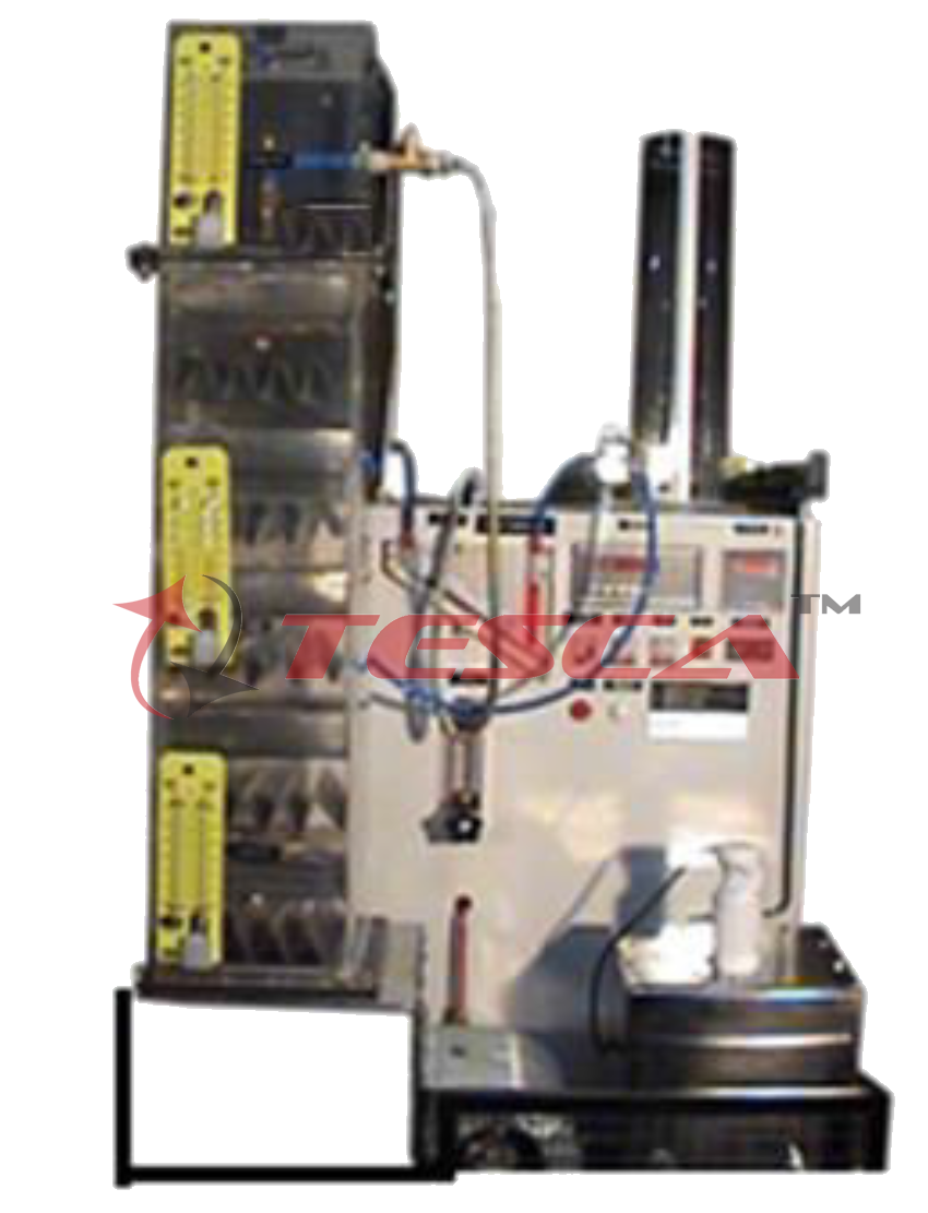
Order Code: 32294
Category: Thermodynamics Lab
Features Designed to demonstrate operation forced draught cooling tower & investigate its performance. Comprehensive Instrumentation Panel with all necessary measuring instruments. Optional Real time Data Acquisition System with graphical disp...
SPECIFICATION
Features
Designed to demonstrate operation forced draught cooling tower & investigate its performance.
Comprehensive Instrumentation Panel with all necessary measuring instruments.
Optional Real time Data Acquisition System with graphical display.
Optional Multi-media Inter-active learning software: SCI-CALS
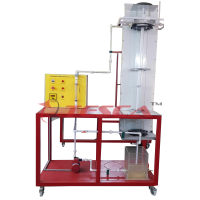
Tesca Water Cooling Tower 32294 has been designed to allow engineering students to get familiarized with all the processes related to industrial force draught cooling tower. The basic unit can be used with other columns to further assist students in the study Refrigeration & Air conditioning, Heat & Mass Transfer.
It consists of a Packed cooling tower with blower fan at bottom. Hot water is sprayed at the top & cold water is collected at bottom of tower. Air is forced from bottom of the tower & leaves from the top. A hot water tank generates hot water & a pump supplies this hot water to the cooling tower. Measuring Instruments are included to measure temperature of water & air at different points, Flow rate of water & air. All the sensors are connected to the Data Acquisition System & the acquired data is processed by the software. The software displays the data & results are shown in tabular format.
Detailed Operation & Maintenance Manual is provided along with the trainer.
Specifications
Stainless steel structure, table-top dimensions
Cooling Tower: Height 600mm transparent cooling tower of Plexigas, with demister
Centrifugal fan for cooling
Stainless steel tank for hot water: 10 liters capacity, including 3 electrical heaters (500 W)
Reserve: Plexigas tank for water, 1 liter capacity.
Water pump: max. flow 3m³lh, max height 5 m H?O approx
Instrument:
6 digital LCD thermometers (2 for dry bulb, 2 for wet bulb, 1 for the water input and 1 for the output water)
Calibrated orifice flow-meter range 20-200 I/h approx.,
Inclined manometer 0-60 mm H?O approx,
Digital thermostat
3 packings/Cooling Towers available, with different surfaces
Data Acquisition System & the acquired data is processed by the software (optional)
Electrical control panel, IP55 protection grade with electrical diagram under CE standards, including contactors, ELCB, start/stop pushbuttons, indicating lamps, fan controls etc.
Technical Specifications
Water propeller pump, computer controlled, maximum flow of water: 120 l./h.
Air propeller with a fan with speed control from the computer (PC), (145 m3/h max., 3000 rpm).
Heating element, computer controlled, (60º C. max.).
Water tank (14 l. capacity).
Level switch in the tank.
Flow sensor, range: 0.25 - 6.5 l./min.
2 Differential pressure sensors, range: 0 - 1” H2O.
Up to 16 temperature sensors type “J” (of wet bulb, dry bulb and water temperature), according to the column supplied.
Column included:
Column type B: Nº of levels: 8. Nº of sheets by level: 10. Total surface: 1.013 m2. Height of packaging: 650 mm. Density Area/volume: 58 m2/m3.
Optional
‘Sci-Cal’ Computer Control Software
PID Computer Control + Data Acquisition + Data Management.
Compatible with actual Windows operating systems. Graphic and intuitive simulation of the process in screen. Compatible with the industry standards.
Registration and visualization of all process variables in an automatic and simultaneous way.
Flexible, open and multi-control software, developed with actual windows graphic systems, acting simultaneously on all process parameters.
Analog and digital PID control.
Menu for PID and set point selection required in the whole work range.
Management, processing, comparison and storage of data.
Sampling velocity up to 250 KS/s (Kilo samples per second).
Calibration system for the sensors involved in the process.
It allows the registration of the alarms state and the graphic representation in real time.
Comparative analysis of the obtained data, after the process and modification of the conditions during the process.
Open software, allowing to the teacher to modify texts, instructions. Teacher’s and student’s passwords to facilitate the teacher’s control on the student, and allowing the access to different work levels.
This unit allows the 30 students of the classroom to visualize simultaneously all results and manipulation of the unit, during the process, by using a projector or an electronic whiteboard.
This module requires Control Interface Module and Data Acquisition.
Interface In-built Module:
This control interface is common for the ‘Sci-tech’ trainers and can work with one or several trainers.
The Control Interface is part of the SCADA system.
Control interface with process diagram on the front panel.
The unit control elements are permanently computer controlled.
Simultaneous visualization in the computer of all parameters involved in the process.
Calibration of all sensors involved in the process.
Real time curves representation about system responses.
All the actuators’ values can be changed at any time from the keyboard allowing the analysis about curves and responses of the whole process.
Shield and filtered signals to avoid external interferences.
Real time PID control with flexibility of modifications from the computer keyboard of the PID parameters, at any moment during the process.
Real time PID control for parameters involved in the process simultaneously.
Proportional control, integral control and derivative control, based on the real PID mathematical formula, by changing the values, at any time, of the three control constants (proportional, integral and derivative constants).
Open control allowing modifications, at any moment and in real time, of parameters involved in the process simultaneously.
Three safety levels, one mechanical in the unit, another electronic in the control interface and the third one in the control software.
Experiment Capabilities
To study the water flow pattern and distribution.
To measure all “end states”, and flow rates of water air and make-up water.
To plot the end states on a psychometric chart and to draw up energy balances using the steady flow equation.
To study the performance at different range of cooling loads and inlet temperatures.
Services Required
Electric Supply 220 - 240V AC, 16 A, Single Phase, Earthed.
Tap water supply & Drainage.
Cables and Accessories, for normal operation.
Manuals: Required Services, Assembly and Installation, Interface and Control Software, Starting-up, Safety, Maintenance, Calibration & Practices Manuals.
Cooling Column Type 2 : Order Code - 32294A Features
Cooling column contains large wet deck surface
Cooling columns contain wet deck surfaces. The cooling capacity of a cooling column is determined by the surface of these wet deck surfaces.
Tesca Cooling Column Type 2 32294A contains a large wet deck surface. The cooling column type 3 is placed into 32294 instead of the column type 2. The cooling capacity of both columns is compared.
On top of the cooling column, a nozzle is mounted. The hot water is sprayed at the top of the cooling tower, trickles from the top to the bottom along the wet deck surface and is cooled in the process. The air enters the column from the bottom and flows upwards.
The cooling column is fitted with connections for differential pressure measurement at its inlet and outlet.
Specifications
Additional cooling column for the wet cooling tower 32294
Cooling column made of transparent plastic
Wet deck surface made of plastic
Connections to measure the pressure loss with 32294
Technical Specifications
Specific surface of the wet deck surface: 77m²/m³
Cross-section: 150x150mm
Order Code 32294A
Experiments
- Determination of the cooling capacity
Cooling Column Type 3 : Order Code - 32294B
Features
Cooling column contains large wet deck surface
Cooling columns contain wet deck surfaces. The cooling capacity of a cooling column is determined by the surface of these wet deck surfaces.
Tesca Cooling Column Type 3 32294B contains a large wet deck surface. The cooling column type 3 is placed into 32294 instead of the column type 1. The cooling capacity of both columns is compared.
On top of the cooling column, a nozzle is mounted. The hot water is sprayed at the top of the cooling tower, trickles from the top to the bottom along the wet deck surface and is cooled in the process. The air enters the column from the bottom and flows upwards.
The cooling column is fitted with connections for differential pressure measurement at its inlet and outlet.
Specifications
Additional cooling column for the wet cooling tower 32294
Cooling column made of transparent plastic
Wet deck surface made of plastic
Connections to measure the pressure loss with 32294
Technical Specifications
Specific surface of the wet deck surface: 200m²/m³
Cross-section: 150x150mm
Experiments
Determination of the cooling capacity
Order Code 32294B
Cooling Column Type 4 : Order Code - 32294C
Features
Cooling column contains large wet deck surface
Use of wet deck surfaces of your own design
Tesca Cooling Column Type 4 32294C contains a cooling column without a wet deck surface. The cooling column type 4 is placed into TH 038 instead of the column type 1. The heat transfer in the free water drop can be studied using this cooling column. It is also possible to insert wet deck surfaces of your own design into the cooling column. The cooling capacity of the different columns is compared.
On top of the cooling column, a nozzle is mounted. The hot water is sprayed at the top of the cooling tower, trickles from the top to the bottom along the wet deck surface and is cooled in the process. The air enters the column from the bottom and flows upwards.
The cooling column is fitted with connections for differential pressure measurement at its inlet and outlet.
Specifications
Additional cooling column for the wet cooling tower 32294
Cooling column made of transparent plastic
Wet deck surface made of plastic
Connections to measure the pressure loss with 32294
Technical Specifications
Packing density: 0m²/m³
Cross-section: 150x150mm
Experiments
- Determination of the cooling capacity
Cooling Column Type 5 : Order Code - 32294D Features
Cooling column contains large wet deck surface
Use of wet deck surfaces of your own design
Order Code 32294C
Cooling columns contain wet deck surfaces. The cooling capacity of a cooling column is determined by the surface of these wet deck surfaces.
Tesca Cooling Column Type 5 32294D contains divided wet deck surfaces. The cooling column type 5 is placed into 32294 instead of the column type 1. It is possible to variably arrange the wet deck surfaces. Additionally, plates are fitted into the cooling column. The cooling capacity of both columns is compared.
On top of the cooling column, a nozzle is mounted. The hot water is sprayed at the top of the cooling tower, trickles from the top to the bottom along the wet deck surface and is cooled in the process. The air enters the column from the bottom and flows upwards.
The cooling column is fitted with connections for differential pressure measurement at its inlet and outlet. A temperature sensor measures the water temperature at the plates. The values are processed and indicated in 32294.
Specifications
Additional cooling column for the wet cooling tower TH 038: @ 900mm
Cooling column made of transparent plastic
Wet deck surface made of plastic, variably arranged
Cooling column fitted with plates
Sensor to measure the water temperature
Connections to measure the pressure loss with TH 038
Order Code 32294D
Technical Specifications
specific surface: variable
Number of plates: 3
Cross-section: 150x150mm
Experiments
Determination of the cooling capacity




 91-9829132777