
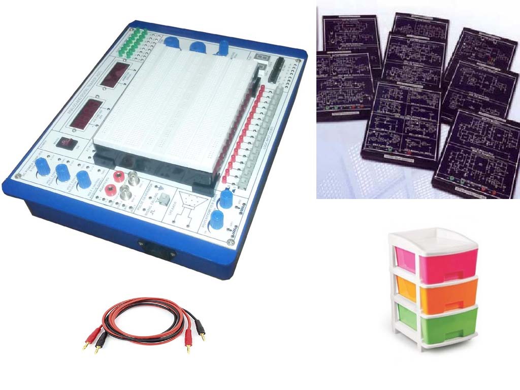
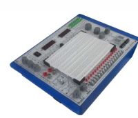
COMPLETE TRAINING SYSTEM FOR STUDY OF DISCRETE COMPONENTS AND BASIC ELECTRONIC CIRCUITS, OSCILLATORS AND ACTIVE FILTERS
Order Code: 24257358.1.9
Category: General Lab Equipment V
Covers the following electronic components and their characterstics. Diode characteristics Exercise 1: Diode as a valve in a circuit Exercise 2: Static recording of the current-voltage characteristics Exercise 3: Dynami...
SPECIFICATION
Covers the following electronic components and their characterstics.
Diode characteristics
-
Exercise 1: Diode as a valve in a circuit
-
Exercise 2: Static recording of the current-voltage characteristics
-
Exercise 3: Dynamic representation of the current- voltage characteristic
-
Exercise 4: The differential resistance of diodes
Single-pulse rectifier circuit M1U
-
Exercise 1: The output voltage Vout(t) for an ohmic load
-
Exercise 2: The output voltage as a function of the load capacitor
-
Exercise 3: The output voltage as a function of the load resistor
-
Exercise 4: Determining the reverse voltage
Two-pulse midpoint rectifier M2U
-
Exercise 1: The output voltage vout(t) for an ohmic load
-
Exercise 2: The output voltage as a function of the charging capacitor
-
Exercise 3: The output voltage as a function of the load resistor
-
Exercise 4: Determining the reverse voltage
Two-pulse bridge-rectifier circuit B2U
-
Exercise 1: The output voltage v out (t) for an ohmic load
-
Exercise 2: The output voltage as a function of the charging capacitor
-
Exercise 3: The output voltage as a function of the load resistor
-
Exercise 4: Determining the diode current
-
Exercise 5: Determining the reverse voltage across the diode V1
Smoothing and filtering
-
Exercise 1: Representing the ripple voltage on the load voltage
-
Exercise 2: The ripple voltage as a function of charging capacitor and load resistor
-
Exercise 3: Measuring and calculating the ripple voltage
-
Exercise 4: The influence of an RC filter on the ripple voltage
LED characteristic
-
Exercise 1:Dependence of the emittence of light from an LED on the polarity of the operating voltage
-
Exercise 2:Static current-voltage characteristic IF = f(VF) of a red LED and of an infrared? LED
-
Exercise 3: Dynamic representation of the current- voltage characteristic IF = f(UF) of a red, an infrared and a green LED
-
Exercise 4: Threshold voltages of LEDs
Zener diode characteristics
-
Exercise 1: Static current-voltage characteristic IZ= f(VZ) of Zener diode
-
Exercise 2: Dynamic representation of the current- voltage characteristic IZ= f(VZ) of a Zener diode
-
Exercise 3: Determining the working point P(VZ, IZ)
-
Exercise 4: Differential resistance of Zener diodes
Voltage stabilization with Zener diode
-
Exercise 1: Representing the output voltage characteristic V out= f(V in ) as a function of the selected Zener diode
-
Exercise 2: Influence of load resistance and load current on the output voltage
-
Exercise 3: Stabilizing a pulsing dc voltage Exercise 4: Calculating the stabilization factors
VDR characteristic
-
Exercise 1:Static recording of the current-voltage characteristic I = f(V) of a voltage-dependent resistor
-
Exercise 2: Determine the operating point P(V VDR ,I)
-
Exercise 3:Dynamic representation of the current-voltage characteristic I = f(V) of a voltage-dependent resistor.
-
Exercise 4: Using the VDR as a voltage limiter
Transistor input characteristic
-
Exercise 1: Base-emitter diode characteristic for open collector
-
Exercise 2: Influence of the collector voltage on the input characteristic
-
Exercise 3: Static and differential input resistance
Control characteristic with current amplification
-
Exercise 1:Representing the relationship IC(IB) with VCE as parameter, i.e.VCE = constant
-
Exercise 2: Static current amplification
-
Exercise 3: Dynamic current amplification
-
Exercise 4:Transposing the operating point inside the characteristic fields IB(VBE), IC(IB) and IC(VCE)
Transistor output characteristic
-
Exercise 1:Measurement method for determining the relation between VCE?and I C
-
Exercise 2:Recording the parameters in tables
-
Exercise 3:Representing the parameters in the output characteristics field
Common emitter
-
Exercise 1:Setting the working point
-
Exercise 2:Voltage division and dc losses
-
Exercise 3:Working point stabilization
Emitter Amplifier
-
Exercise 1:Voltage gain
-
Exercise 2:Current gain
-
Exercise 3:AC power
Negative current feedbackin the emitter amplifier
-
Exercise 1Influence of the emitter capacitor C E on the voltage gain
-
Exercise 2: Frequency response of the voltage gain
-
Exercise 3:m Overdrive
-
Exercise 4:Input resistance
Common base
-
Exercise 1: Working point setting and function of common base
-
Exercise 2: Input resistance and gain factors
-
Exercise 3: Phase and HF properties
Common Collector
-
Exercise 1:Working point setting and stabilization
-
Exercise 2:Gain factors
-
Exercise 3:Input and output resistances for ac current
Transistor as switch
-
Exercise 1:Transistor with control circuit and switching circuit - current gain
-
Exercise 2:Base current for reliable switching
-
Exercise 3: Power losses of a switching transistor
-
Exercise 4:Control with square-wave generator
Characteristics of a FET
-
Exercise 1:Self-conduction of the depletion layer FET
-
Exercise 2:Working ranges for control voltage and current
-
Exercise 3:Output characteristics field with VGS as parameter
-
Exercise 4:Input characteristic with VDS as parameter
Interpreting the characteristics of a FET
-
Exercise 1:Displaying output characteristics with the oscilloscope
-
Exercise 2:Transferring the oscillogram to a scaled output characteristics field
-
Exercise 3:Determining the dynamic output resistance rout?at different working points
-
Exercise 4:Displaying input characteristics with the oscilloscope
-
Exercise 5:Transferring the oscillogram to a scaled input characteristics field
-
Exercise 6:Determining the slope S for different working points
Properties of phototransistors
-
Exercise 1:Photocurrent resulting from radiant exposure to an LED
-
Exercise 2:Spectral sensitivity of the phototransistor
-
Exercise 3:Qualitative examination of the characteristic
Optocoupler with phototransistor and LED
-
Exercise 1: Principle of dc decoupling by means of an optocoupler
-
Exercise 2: Working point conditions
-
Exercise 3: Discrete optocoupler acting as a pulsating voltage amplifier
-
Exercise 4: Frequency response
Diac characteristic and application
-
Exercise 1: Representation of the current/voltage characteristic I = f(V)
-
Exercise 2:Determining the positive and negative breakdown voltage Vr, F, VBr,R
-
Exercise 3:Determining the residual voltages VF, VR and the return voltages VF, VR
-
Exercise 4: Generating trigger pulses for triac control
Thyristor characteristics
-
Exercise 1: Thyristor as a controllable valve
-
Exercise 2: Dynamic representation of the current- voltage characteristic IG= f (VG) of the gate cathode path.
-
Exercise 3: Dynamic representation of the current- voltage characteristic IF= f(VF)
Thyristor in dc circuit
-
Exercise 1: Determine typical values for thyristor triggering
-
Exercise 2: Measure the minimum current necessary for operation
-
Exercise 3: Turning off a thyristor by means of capacitor discharge
Thyristor in ac circuit
-
Exercise 1: Representing the voltage curve VL at the load and the characteristic of the gate current IG
-
Exercise 2: Determine the trigger angle and the current flow angle from the VL voltage curve
-
Exercise 3: Representing the voltage curves of VT and VL for > 90°
Triac characteristic
-
Exercise 1: Oscillogram of the triac characteristic for specified gate current
-
Exercise 2: Representing the triac as an anti-parallel circuit of two thyristors
-
Exercise 3: Dependence of the triac voltage VT= VA2, A1 on the gate current IG
Phase control with triac
-
Exercise 1: The operating principle of the triac as a controllable valve
-
Exercise 2: Setting the control angle
-
Exercise 3: Function of the trigger pulse circuit Discrete Components:
-
1 Resistor 10 ohm, 2 W
-
1 Resistor 100 ohm, 2 W
-
1 Resistor 330 ohm, 2 W
-
1 Resistor 470 ohm, 2 W
-
1 Resistor 1 kohm, 2 W
-
1 Resistor 1.5 kohm, 2 W
-
1 Resistor 2.2 kohm, 2 W
-
1 Resistor 3.3 kohm, 2 W
-
1 Resistor 10 kohm, 0.5 W
-
1 Resistor 47 kohm, 0.5 W
-
1 Resistor 100 kohm, 0.5 W
-
1 Resistor 1 Mohm, 0.5 W
-
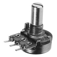
1 Potentiometer 1 kohm, 1 W
-
1 Potentiometer 10 kohm, 1 W
-
1 Potentiometer 100 kohm, 1 W
-
1 Voltage dependent resistor
-
1 Capacitor 100 pF, 160 V
-
1 Capacitor 22 nF, 100 V
-
1 Capacitor 0.1 µF, 100 V
-
1 Capacitor 1 µF, 100 V
-
1 Capacitor 2.2 µF, 63 V
-
2 Capacitors 4.7 µF, 63 V
-
1 Capacitor 10 µF, 35 V
-
1 Capacitor 47 µF, 40 V
-
1 Capacitor 100 µF, 35 V
-
1 Capacitor 470 µF, 16 V
-
1 Light emit. diode infrared, lateral
-
1 Ge diode AA 118
-
4 Si diodes 1N 4007
-
1 Z diode ZPD 9.1
-
1 Z diode ZPD 6.2
-
1 LED1, green, top, LEGED 1 LED1, green, top, LEGED
-
1 LED red, lateral
-
1 Diac BR 100
-
1 Photo-diode BPX 43
-
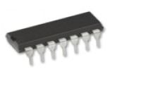
1 Transistor BD 137 (NPN), e.b.
-
1 Fe-transistor BF 244
-
2 Thyristors TYN 1012 1 Triac BT 137/800
-
1 Inductance 33 mH
-
2 Lamp holders E10, top 2 Key switch, single-pole
-
1 Set 10 incand. lamps 12 V/3 W, E10
-
1 Tray
-
2 Capacitors 4.7 µF, 63 V
-
1 Capacitor 10 µF, 35 V
-
1 Capacitor 47 µF, 40 V
-
1 Capacitor 100 µF, 35 V
-
1 Capacitor 470 µF, 16 V
-
1 Light emit. diode infrared, lateral 1 Ge diode AA 118
-
4 Si diodes 1N 4007
-
1 Z diode ZPD 9.1
-
1 Z diode ZPD 6.2
-
1 LED1, green, top, LEGED 1 LED1, green, top, LEGED 1 LED red, lateral
-
1 Diac BR 100
-
1 Photo-diode BPX 43
-
1 Transistor BD 137 (NPN), e.b.
-
1 Fe-transistor BF 244
-
2 Thyristors TYN 1012 1 Triac BT 137/800
-
1 Inductance 33 mH
-
2 Lamp holders E10, top 2 Key switch, single-pole
-
1 Set 10 incand. lamps 12 V/3 W, E10
-
1 Tray
-
Enquiry Form
Related Product


Tesca specialize in doing turnkey projects that is fully operable when it is handed over to the project authority. Starting from inception to application training, Tesca provides the services as ONE source solution. Working side by side with government authorities and people across the World, we help countries to perform better. We support countries grow their economies, strengthen their education and health systems and improve financial management. We do this by providing consultancy & training in environment safety, education, health strengthening.
Category
Useful Links
Contact Us
International Sales:
 91-9829132777
91-9413330765
India Sales:
91-9588842361
2025 © All Rights Reserved.