ASK Modulation
Order Code: 22236079.4.33
Category: General Lab Equipment I
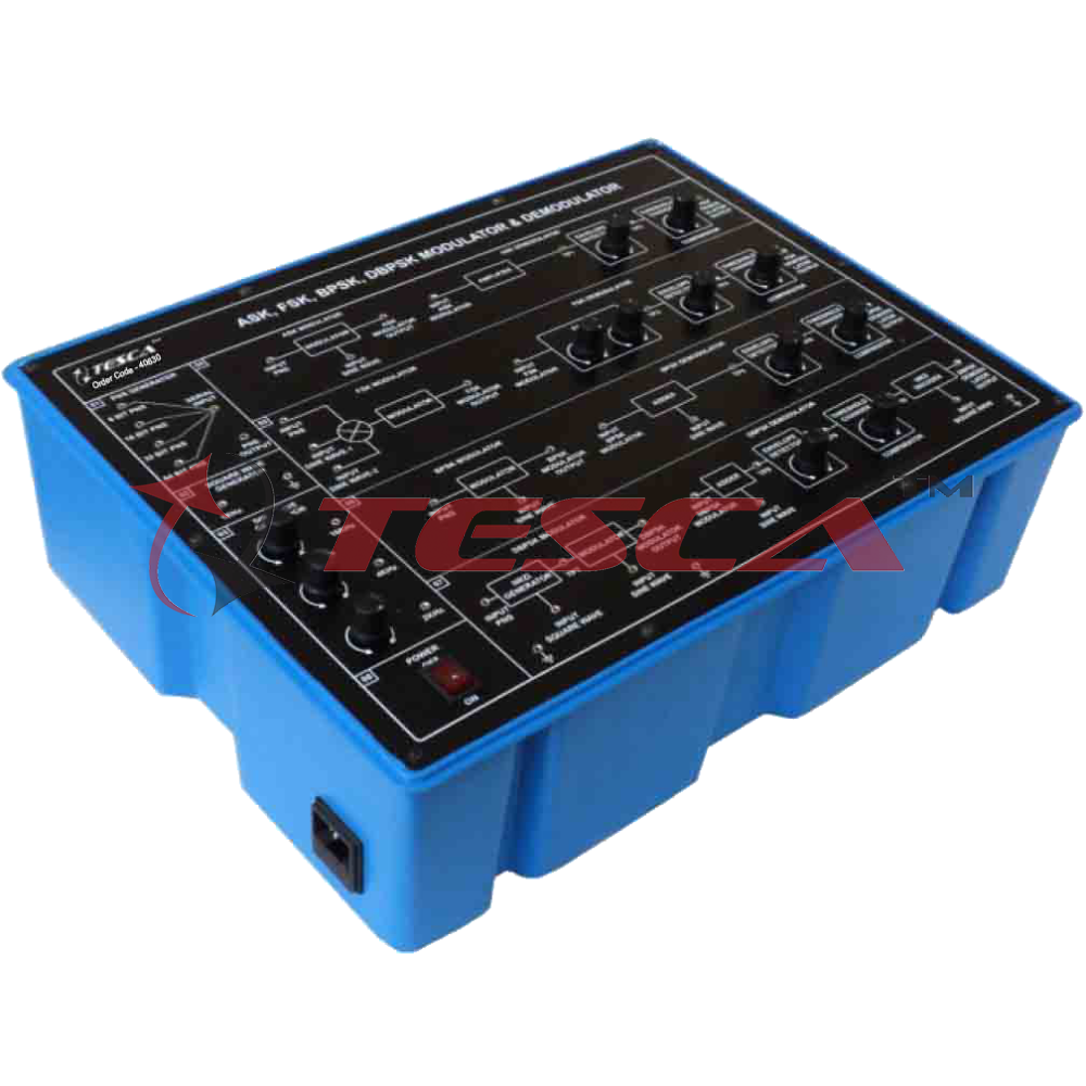
Panels made in metal case with bench support and the electrical scheme on the front panel. The board must consist of ASK (Amplitude Shift Keying) modulator and demodulator sections that can be interconnected in order to simulate a complete transmissi...
SPECIFICATION
Panels made in metal case with bench support and the electrical scheme on the front panel. The board must consist of ASK (Amplitude Shift Keying) modulator and demodulator sections that can be interconnected in order to simulate a complete transmission system. Technical features: The board must use the support board as a service module to provide the carrier signal, the modulating random digital signal, the error rate meter and the line simulator. CMOS static switch modulator with output buffer and demodulator. The board shall include the following elements: NRZ encoder: it must encode the TTL level signal coming from the auxiliary generator into signals having bipolar NRZ line code. Duo-binary encoder: it must be used to study the operation of the ASK partial response transmission system. AM modulator: it must be able to operate with digital modulating signals. This module shall require the connection with the auxiliary carrier generator. The modulation index shall be variable by means of a suitable drive (MODULATION). Receiver: it must be composed of an intermediate frequency amplifier (IF), signal generator for the automatic gain control and input attenuator to carry out the AGC (Automatic Gain Control) function. AM detector: it must be composed of a simple envelope detector circuit with diode and low-pass filter. NRZ decoder: it must accept in input the signal produced from the envelope detector and it operates in base to a timing generated in the receiver from the clock regenerator. The NRZ decoder shall be equipped with a variable decision threshold used internally to distinguish between the logic levels of the received signal. Duo-binary decoder: it must allow to study the operation of the partial response ASK system. The circuit shall use the clock supplied by the regenerator circuit of the receiving section and it shall be equipped with a manual drive (DECISION POINT) to determine the level recognition thresholds. Reception clock regenerator: this module shall simulate the extraction and regeneration circuit of the timing signal present in the receiving terminal of any data transmission system. The clock regenerator shall be composed by a PLL (Phase Locked Loop) which can be synchronized with the transitions of the received signal. For its nature, the circuit can synchronize with the frequency of the clock used for the transmission and also with its harmonics and sub-harmonics. To make the educational use easier, this regenerator clock shall be equipped with a manual check of the PLL (f ADJ) free oscillation frequency, so that the PLL itself is carried manually to lock to the fundamental frequency of the transmission clock. For an immediate verification of the right lock, the regenerator shall be equipped with a Led (LOCK) that switch on when the regenerated clock coincides with the transmission one. The clock regenerator shall be equipped with a phase shifter allowing to dephase the (rise) active edge of the clock of about 180 degrees, for especial test purposes. It will be possible to notice that, if we change the bit rate (transmission speed or transmission clock frequency) it will be necessary to adjust again both the PLL free frequency, for the lock to the new frequency, and the regenerated clock phase, to reset the receiver operation. With this board it must be possible to perform the following exercises: ASK systems architecture, ASK modulation/demodulation procedure, Error rate measurement as a function of different transmission speed and of the characteristics of imperfect transmission media (attenuation, noise), Operation of the panel, ASK system with NRZ line code, Partial response ASK system with duo-binary coding, ASK system with NRZ code in presence of transmission noises, Partial response ASK system with duo-binary coding in presence of transmission noises. It must be mounted on an insulated didactic module, it must show a schematic diagram and 2 mm terminals for the electrical connection. The board must be supplied complete with a set of stackable, plug-in cables of suitable lengths and colours and with a training manual.






 91-9829132777