
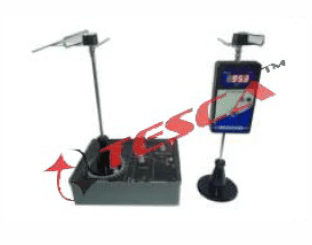
Antenna Training System
Order Code: 24257841.1
Category: General Lab Equipment V
Antenna Training System - Key Features Diverse Antenna Selection: A wide variety of antennas are available, designed for operation within the 500 MHz RF range. Each antenna is equipped with BNC (F) connectors for easy integration with RF g...
SPECIFICATION
Antenna Training System - Key Features
-
Diverse Antenna Selection:
A wide variety of antennas are available, designed for operation within the 500 MHz RF range. Each antenna is equipped with BNC (F) connectors for easy integration with RF generators and power meters. Antennas can be swapped quickly using M8 screws and wing nuts. -
Operational Modes:
Supports both standalone and PC-based operation modes. -
PC Interface:
Optional PC-based auto mode requires a stepper driver and CIA panel with compatible software (Windows XP/7). -
Data Acquisition:
Direct USB interface allows for power meter reading acquisition. -
Comprehensive Documentation:
Includes a detailed Student Workbook (SW) and Instructor's Guide (IG), which feature filled tables and plotted polar graphs.
Technical Specifications of Subsystems
-
RF Signal Generator / RF-6:
-
Frequency Range: 10 MHz to 600 MHz
-
Output Power: +3 dBm to –27 dBm (amplitude at 50 Ω impedance)
-
Display: 4.5-digit Red 7-segment display
-
-
RF Power Meter / RFM-5M:
-
Input Power Range: 15 dBm to –60 dBm (max: 20 dBm)
-
Frequency Range: 10 MHz to 500 MHz
-
Display: 4.5-digit Red 7-segment display
-
PC Interface: USB interface for data plotting
-
Mode Selection: Online/Offline mode via DPDT switch
-
Impedance: 50 Ω input impedance
-
-
Transmitting & Receiving Masts:
-
Construction: Aluminium rotating table base (180 x 180 mm), optional 2 kg-cm stepper motor on the transmitting mast
-
Mast Specifications: Stainless steel pipe (Height: 600 mm, Diameter: 19 mm)
-
Angle Measurement: Scale with pointer for rotation angle measurement
-
-
Directional Coupler / MS-1:
-
Frequency Range: 50–2000 MHz, bi-directional
-
Purpose: For Return Loss and VSWR measurements
-
Coupling Factor: 10 dB
-
Connector Type: All ports equipped with BNC Female sockets, including two 50 Ω BNC terminations
-
-
Stepper Driver Panel / P-25 (Optional):
-
Functionality: Programmable stepper control with built-in power for CW & CCW rotation
-
Stepping Modes: 0.90° (Half-step mode) and 1.80° (Full & Wave-drive modes)
-
Motor Compatibility: Drives 2 kg-cm stepper motor via 15-pin D connector
-
-
PC-Based Graph Utility Software (Optional):
-
Modes: ONLINE or OFFLINE, supporting fully automatic, semi-automatic, or manual operation
-
Editing Features:
-
Rotation angle per step: 0.00° to 99.90°
-
Clock pulses per step: 1 to 99
-
Time-gap between clock pulses: 0.1 to 9.9 seconds
-
Calibration of polar plot scale for power meter readings
-
Data storage and offline plotting capabilities
-
-
List of Experiments
-
Observation of antenna radiation patterns (manual or PC-based)
-
Absolute and relative gain measurements of antennas
-
Measurement of antenna beam-width
-
Evaluation of antenna front-to-back ratio
-
Return loss and VSWR measurements using directional coupler
-
Study of polarization principles
-
Impedance matching using Smith Chart
-
Investigation of antenna resonance
-
Measurement of scattering parameters
Antenna Set Selection
Choose at least ten antennas from the following options (customizable based on requirements):
| Antenna Type | Elements | Lengths (mm) | Material | Dimensions (L x W, mm) |
|---|---|---|---|---|
| Half-wave Folded Dipole | 1 | 300 (Folded) | Aluminium pipe | 115 x 330 |
| Yagi-Uda 3-element | 3 | 300, 275, 300 | Aluminium pipe | 250 x 330 |
| Yagi-Uda 5-element | 5 | 300, 275, 260, 245, 300 | Aluminium pipe | 500 x 330 |
| Yagi-Uda 7-element | 7 | 300, 275, 260, 245, 230, 215, 300 | Aluminium pipe | 500 x 330 |
| Half-wave Simple Dipole | 2 | 300, 300 | Aluminium pipe | 120 x 330 |
| 3λ/2 Simple Dipole | 2 | 450, 450 | Aluminium pipe | 115 x 920 |
| Quarter-wave Simple Dipole | 2 | 75, 75 | Aluminium pipe | 115 x 180 |
| Half-wave Folded Dipole with Reflector | 2 | 300, 300 | Aluminium pipe | 250 x 330 |
| Circular Loop | 1 | 600 | Aluminium pipe | Length: 115, Height: 230 |
| Log Periodic | 14 | Varied | Aluminium pipe | 740 x 760 |
| Helical | 1 | 3-turns (Dia: 600) | Aluminium pipe | Length: 250, Height: 520 |
| Half-wave End-Fire | 4 | 150 | Aluminium pipe | 360 x 330 |
| Quarter-wave End-Fire | 4 | 150 | Aluminium pipe | 250 x 330 |
| Broad-side Array | 12 | 150 | Aluminium pipe | 500 x 330 |
| Co-linear | 4 | 150 | Aluminium pipe | 360 x 330 |
| Slot | 1 | 60 x 300 (slot) | Copper clad PCB | 300 x 450 |
| Discone | 1 | Dia: 132 (Disc) | Galvanized Iron | 250 x 220 x 190 |
| Parabolic Reflector | 1 | Dia: 300 | Galvanized Iron / MS | 300 x 260 x 300 |
| Microstrip Patch | 1 | 176 x 137 (Patch) | Copper patch PCB | 193 x 260 |
| Variable Length (Simple Dipole) | 2 | 300 to 1200 (Adjustable) | Steel rod | 120 x 1300 (Variable width) |
Enquiry Form
Related Product


Tesca specialize in doing turnkey projects that is fully operable when it is handed over to the project authority. Starting from inception to application training, Tesca provides the services as ONE source solution. Working side by side with government authorities and people across the World, we help countries to perform better. We support countries grow their economies, strengthen their education and health systems and improve financial management. We do this by providing consultancy & training in environment safety, education, health strengthening.
Category
Useful Links
Contact Us
International Sales:
 91-9829132777
91-9413330765
India Sales:
91-9588842361
2025 © All Rights Reserved.