
Air Conditioning and Climate Control Trainer
Order Code: AT0025
Category: Automotive Trainers
Description Air-conditioning system trainer A system with an orifice tube Electronic climate control system CLIMATRONIC A fully functional system with R134a refrigerant Diagnosis through OBD 16 pole diagnostic...
SPECIFICATION
Description
-
Air-conditioning system trainer
-
A system with an orifice tube
-
Electronic climate control system CLIMATRONIC
-
A fully functional system with R134a refrigerant
-
Diagnosis through OBD 16 pole diagnostic socket
-
Open contacts for measuring of system's components and circuits
-
Fault code simulations.
-
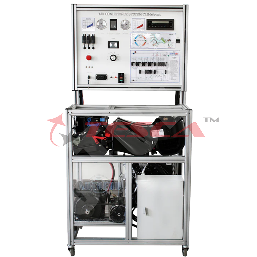
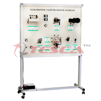
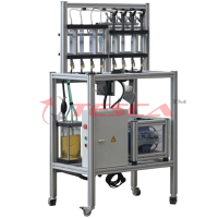
A fully functional air conditioning and climate control system trainer is installed in a mobile aluminum frame. This training board simulator is specially designed to help technical students understand better electronic air conditioning and climate control system CLIMAtronic. The educational training board is based on Audi/VW OEM components. The integrated air conditioning and climate control system shows the different operation modes. Equipment for technical and vocational Tesca education and training.
The training board-simulator is a great educational tool that allows students to learn the structure of air conditioning and climate control system, study its components, and perform various measurements, tests, and other diagnostic procedures to use diagnostic scan tools or other special tools and equipment.
Technical Specifications And Functions
-
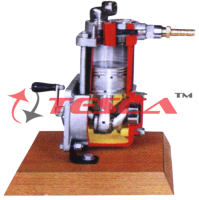
Integrated electronic air conditioning system with climate control (Climatronic) and orifice tube
-
Monitoring operation modes of air conditioning and climate control system
-
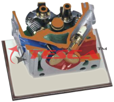
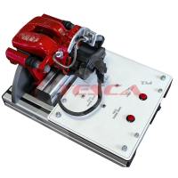
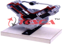
Visible HVAC compressor, electromagnetic compressor clutch, and its operation modes
-
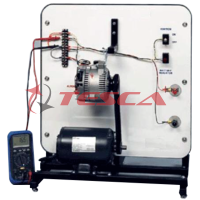
With installed pressure gauges it is possible to monitor the pressure distribution of R134a refrigerant in the high and low-pressure sides (circuits)
-
Visible HVAC (heating, ventilating, and air conditioning) mixing unit with its operation modes
-
Visible the operation of airflow flaps
???????Ability to monitor and control changes of the parameters of each system component:
??????? -
The airflow fan speed
-
The airflow flap positions
-
The interior (inside) temperature
-
The refrigerant R134a pressure changes depending on the speed of the cooling radiator fan
-
The rate of the temperature change depending on the speed of the airflow radiator fan
-
The air flow flap position according to operation modes: defrost, air recirculation (fresh air), or footwell
-
The training board has a diagram with LED's which shows the operation modes of the outlets and flaps
-
The training board has a complete electrical wiring diagram with built-in banana plug jumpers for measurements and simulation of the system fault codes
-
Ability to simulate more than 15 system faults by disconnecting banana plug jumpers. Ability to monitor
-
the changing operation mode of each system component
-
The training board has an integrated voltmeter. It displays the voltage of electronic system components:
-
G92 Control motor potentiometer for temperature flap
-
G114 Control motor potentiometer, footwell/defroster flap
-
G112 Control motor potentiometer, central flap G113 Control motor potentiometer, airflow flap
-
G89 Fresh air intake duct temperature sensor
-
G191 Vent. temperature sender, center
-
G192 Vent. temperature sender, footwell
-
G17 Ambient temperature sensor
-
The integrated thermometer displays the temperature change depending on the pressure of the refrigerant R134a.
Diagnostic and Measurement
Oscilloscope/Multimeter
-
System's parameters are measured by connecting to the banana connector;
-
Ability to measure electrical signal parameters of each system component (such as sensor or actuator)
-
Control unit diagnosis (with the scan tool)
-
Diagnosis through OBD 16-pin diagnostic connector
-
Electronic control unit (ECU) identification
-
Reading/erasing fault codes
-
Displaying the operating system parameters (live data)
-
Activating the actuators (depends on the control unit)
-
Control unit encoding/configuration (depends on the control unit)
-
Control unit diagnosis (manual procedures without the scan tool)
-
Manual diagnostics of Climatronic ECU Error reading - manual procedures
-
Displaying the operating system parameters (live data) - a manual procedure
Other
-
The stand has a closed structure - internal wiring is not visible
-
Power supply: 220V
-
Dimensions approx.: (HxLxW): 1680x800x500mm
-
Nett weight approx.: 100 Kg
-
CE certificate
Optional Accessories
-
Tesca oscilloscope
-
OBD Diagnostic scan tool
-
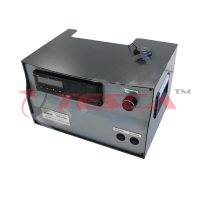
Air conditioning recharge station
Tesca training equipment is a great tool for professional teachers and technicians that helps explain to students of technical subjects how processes in Air conditioning and climate control Educational Trainer MSC01 operates and its technology.
Enquiry Form
Related Product
Tesca specialize in doing turnkey projects that is fully operable when it is handed over to the project authority. Starting from inception to application training, Tesca provides the services as ONE source solution. Working side by side with government authorities and people across the World, we help countries to perform better. We support countries grow their economies, strengthen their education and health systems and improve financial management. We do this by providing consultancy & training in environment safety, education, health strengthening.
Category
Useful Links
Contact Us
International Sales:
 91-9829132777
91-9413330765
India Sales:
91-9588842361
2025 © All Rights Reserved.