
Advanced Hydrology Trainer (2m x 1m)
Order Code: 32060
Category: Fluid Mechanics Lab
Features: Stilled inlet tank provides developed river flow conditions, allowing the full length of the tank to be used for river simulations Unique outlet tank design for water flow and sediment flow measurement SS sand tank: Available from ...
SPECIFICATION
Features:
Stilled inlet tank provides developed river flow conditions, allowing the full length of the tank to be used for river simulations
Unique outlet tank design for water flow and sediment flow measurement
SS sand tank: Available from 1mx2m to 6mx2m; Depths up to 750mm
Dual jacks provide adjustable tilt
Adjustable spray nozzle height
The use of fine grade sand allows detailed feature development
Single grade of sand for all defined demonstrations
Control and measurement of inlet flows
Flexible configuration allows a wide range of simulations
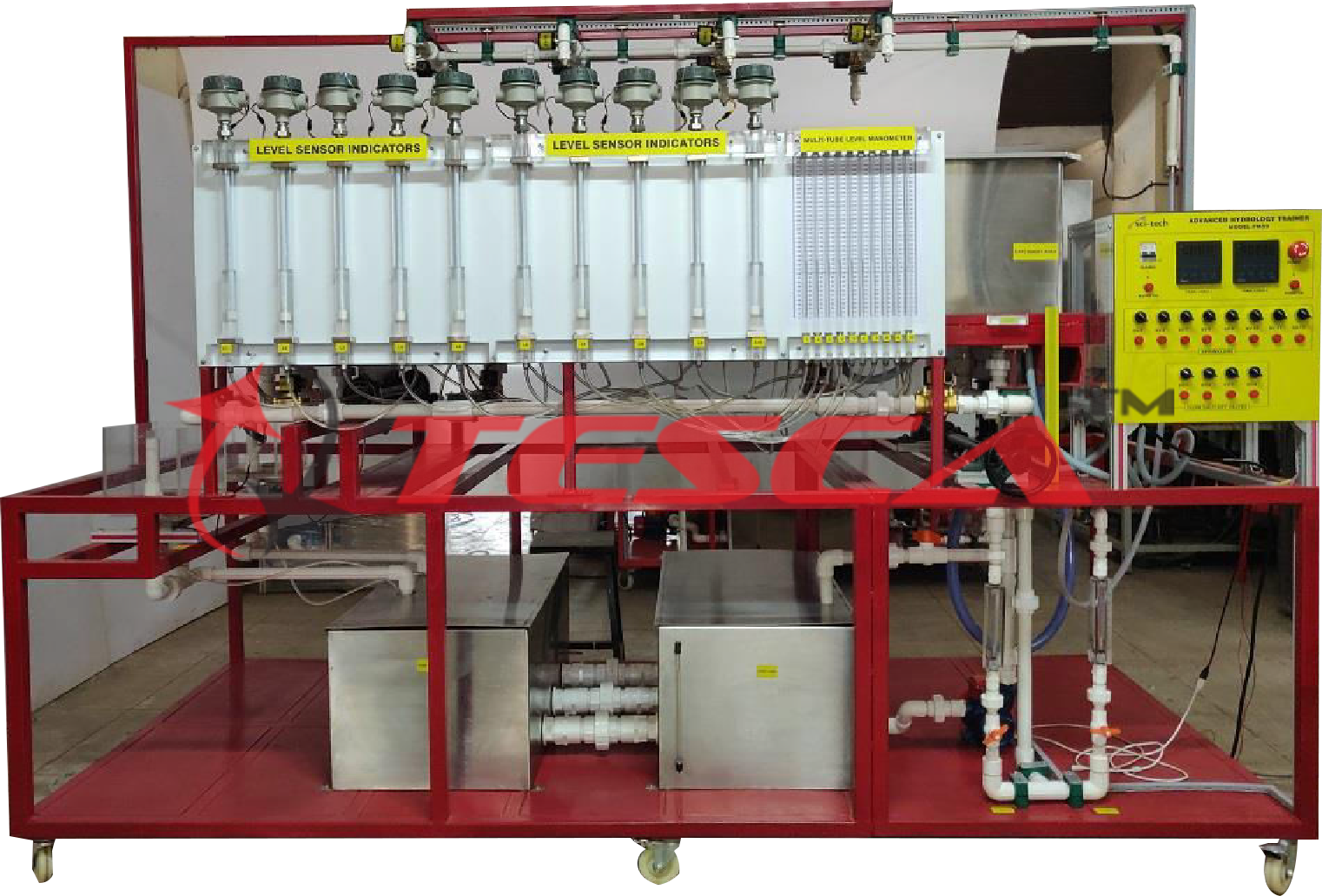
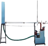
Tesca Advanced Hydrology System Trainer demonstrates some of the major physical processes found in hydrology and fluvial geomorphology, including rainfall hydrographs for catchment areas of varying permeability; the abstraction of groundwater by wells, both with and without surface recharge from rainfall; the formation of river features and effects of sediment transport.
Realistic results can be obtained from this small- scale, floor-standing apparatus, which can be conveniently located and requires no special services. The unit comprises a sand tank, made of stainless steel, measuring 2mtrs by 1mtr ( Optionally available in any required dimensions: We have made up to 6mtrs by 2mtrs). Water may be input to the sand tank from spray nozzles located above the tank (simulating rainfall), from an inlet tank simulating a river flow, or from two drains buried in the sand at either end of the tank. The water is output either from an outlet tank and flow measurement system located at the end of the main sand tank, from one or both of the two wells located in the tank, or one or both of the French drains.
SS or plastic sump tanks are located under the sand tank.
Groundwater table levels (phreatic surface) are measured using eleven to twenty tapping points in the sand tank, configured, optionally in a cruciform pattern, and displayed on a manometer bank. Four to Eight stainless steel spray nozzles, depending on the tank size, are mounted on a gantry above the sand tank, positioned to give an even distribution across the tank surface. The height of the gantry can be easily adjusted. Each nozzle has an associated on/off valve, allowing a wide variety of moving rainfall patterns to be simulated.
The river inlet tank uses glass balls to still the flow, and a shaped channel section to provide formed flow conditions into the sand tank.
The subsurface flow inputs are via two drains, buried in the sand at either end of the tank. These French drains can optionally extend the full width of the tank. Each drain can be configured as an inlet or an outlet to permit a wide variety of hydrological demonstrations.
Variable area flowmeters with integral adjusting valves are used to control and measure the various flows into the tank. The use of self- sealing quick-release fittings allows the system to be configured in a variety of different ways, enabling a wide range of demonstrations. The two flow meters have different ranges, further enhancing the flexibility of the overall system. Pressure regulators (optional) and filters are incorporated in the water supply lines, minimizing system disturbances. The outlet tank is located at the end of the sand tank and is used for hydrographs, run-off, and river formation demonstrations. A stepped height weir is used to adjust the outlet conditions. (When performing water table demonstrations this stepped weir is replaced with a sealing plate.) The outlet tank comprises a sand trap, a water stilling system, and a flow measurement device. The flow measurement is performed by measuring the height of the water flowing over the outlet weir, using a manometer. The sand trap is configured to allow the sediment to be collected in a sieve. In this way, the amount of sediment collected can be measured.
Optionally, additional instrumentation and a data logging system that is used to measure both the water flow and the sediment flow. This system works by measuring the weight of the sand and water collected in the outlet tank and calculating the sediment flow rate from the rate of change of the weight. It comes complete with educational software, helps texts, graph plotting, etc., and requires a user-provided PC.
An optional accessory of sets of shapes and models for use when investigating surface flow effects and run-off effects.
Technical Specifications:
A self-contained floor-standing apparatus for hydrology and f luvial geomorphology demonstrations, comprising:
(a) SS sand tank: Available from 1mx2m to 2mx6m; Depths up to 750mm Stainless steel tank, tiltable using a single or a dual linked jacking system or optionally through Hydraulic jack.
(b) 4 to 6 to 8 stainless steel spray nozzles mounted on an adjustable height gantry
(c) A stilled tank providing a formed flow r i v e r inlet
(d) Two or more flow meters (3L/min & 5L/min) to measure and adjust the inlet flows
(e) Single or two outlet tanks allowing measurement of water and sediment flow
(f) Two French drains, two well points, and 20 manometer tapping points linked to a manometer bank
(g) SS or plastic sump tanks plus recirculating pump
(h) Fine grade 2mm to 5mm sand (Not usually supplied, only against specific requests)
Optional:
DAQ version is available with instrumentation to measure both water and sediment run-off in real-time. The package includes 4 flow Sensors, 8 Level Sensors, Datalogger, LabView 14.0 educational software, (requires a PC).
‘Sci-Cal’ Computer Control Software & Interface (Check separate specifications sheet)
Inflow Pressure regulators
Sand tank cruciform pattern
French drains extension to the full width of the sand tank
Weir Set of shapes and models for use when investigating surface flow effects and run-off effects
Experiment Capabilities:
Run-off hydrographs from model catchments
? Construction of draw-down curves for one or two well systems in a sand bed
Groundwater flow and hydraulic gradients
Model stream flow in alluvial material
Hydraulic gradients in groundwater flow. Investigation of model streamflow in alluvial material
Formation and development of river features over time
Sediment transport, bedload motion, scour, and erosion With optional accessories of sets of shapes and models following experiments can also be possible:
Calculation of concentration-time for a short storm.
Study of the storm hydrograph of an impermeable catchment.
Study of the effect of a moving storm on a flood hydrograph.
Study of the effect of reservoir storage on a flood hydrograph.
Study of the effect of drain pipes on a flood hydrograph.
Investigation of stream flows modeled in alluvial material.
Study of sediment transport, bed-load motion, scour, and erosion.
Required Services:
Coldwater supply (4 liters/min required)
Drain
Electrical supply: 220-240V/1ph/50Hz
1m3 washed well-graded sweetwater gravel, range @2.0 - 5.0mm dia.
Enquiry Form
Related Product


Tesca specialize in doing turnkey projects that is fully operable when it is handed over to the project authority. Starting from inception to application training, Tesca provides the services as ONE source solution. Working side by side with government authorities and people across the World, we help countries to perform better. We support countries grow their economies, strengthen their education and health systems and improve financial management. We do this by providing consultancy & training in environment safety, education, health strengthening.
Category
Useful Links
Contact Us
International Sales:
 91-9829132777
91-9413330765
India Sales:
91-9588842361
2025 © All Rights Reserved.