Stability of Bar Buckling under Load
Order Code: 32159
Category: Strength of Materials Lab
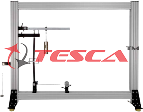
Features Representation of simple stability problems on a buckling bar Determination of the buckling load under different conditions Infinitely variable load application on the buckling bar Buckling is a sta...
SPECIFICATION
Features
- Representation of simple stability problems on a buckling bar
- Determination of the buckling load under different conditions
- Infinitely variable load application on the buckling bar
Buckling is a stability problem which occurs in practice when slim components are subjected to compressive loading. Following a "disturbance" to its equilibrium, such as caused by compressive loading, a stable system returns to equilibrium when the loading is removed. If the compressive load increases excessively, instability of the system results. The component buckles and fails. The critical compressive load at which the system becomes unstable is termed the buckling force.
A simple model for representing stability problems is a two-part bar with an elastic joint which remains stable up to a certain load level. If the buckling force is exceeded, the bar suddenly buckles and so becomes unstable.
Tesca Stability: Bar Buckling under Load is used to investigate simple stability problems on a buckling bar under different conditions. The buckling bar is in two parts, with a central articulated joint. A compressive load is applied to the bar by a lever and weights. The infinitely variable loading is determined precisely with the aid of a scale on the load application lever.
Experiments can depict a variety of conditions, such as an elastic joint or an elastic clamp fixing. Two tension springs serve as the elastic joint. For the elastic clamp fixing option, a steel leaf spring is mounted in the bottom joint. The variable length of the leaf spring means various degrees of clamping are possible. The two cases can be combined.
Another experiment demonstrates the influence of additional shear forces. It involves applying a shear force to the joint in the buckling bar with a cable and a weight.
In all experiments the buckling bar is placed under load until it reaches an unstable situation. The length of the lever arm at which the buckling bar buckles is read from the scale and the buckling force is then determined.
The well-structured instructional material sets out the fundamentals and provides a step-by-step guide through the experiments.
Specifications
Investigation of the buckling load under different conditions (elastic joint, elastic fixed end)
Two-part buckling bar with central joint
Loading infinitely variable with lever and set of weights
Determination of loading via scale on load application lever
Various degrees of clamping via leaf spring with variable length on bottom support
Thrust pad guided friction-free inside spherical shell
Low-friction joints with roller bearings
Device to generate shear forces
Storage system to house the components
Technical Specifications
Two-part buckling bar with central joint
- WxH: 20x20mm
- Length: 2x250mm
- Support: pinned-pinned (articulated-
articulated)
Elastic joint
- 2 tension springs, rigidity: 2N/mm
- Lever arm: 50mm
Elastic clamp fixing with steel leaf spring
- Length: 500mm
- Cross-section: 10x2mm
- 2nd moment of area: 6,66mm4
- Modulus of elasticity: 205000N/mm2
Compressive force range: 25...120N
Shear force: 0...20N
Load application lever, lever ratio: 1:2 - 1:5
Set of weights
- 8x 1N
- 6x 5N
- 2x 1N (hangers)
Experiments
Determination of the buckling force for the case of an:
- Elastic joint
- Elastic fixed end support
Investigation of the buckling behavior under the influence of:
- Of additional shear forces
- Of pre-deformation
Scope of Delivery
- 1 buckling bar, two-part
- 1 set of weights
- 4 supports
- 1 deflection roller
- 1 load application lever
- 1 leaf spring
- 2 tension springs
- 1 cord
- 1 hexagon socket wrench
- 1 storage system with foam inlay
- 1 set of instructional material





 91-9829132777