LFC™_3B Level Control Valve

Order Code: LFC™_3B
Category: Range of Low Pressure Valves
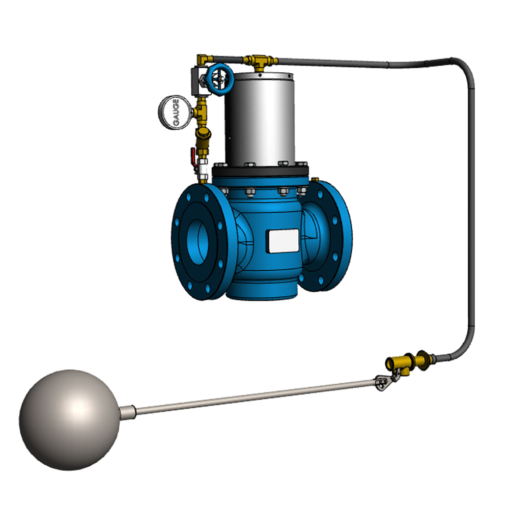
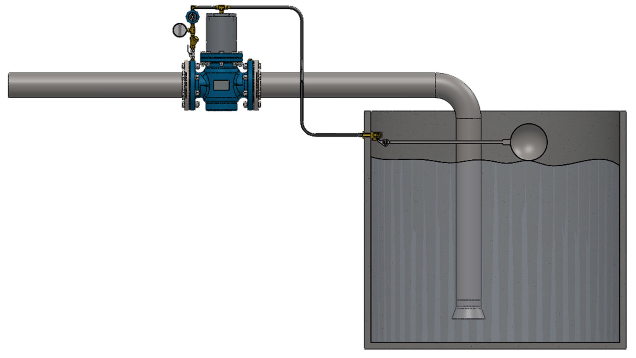
OVERVIEW The LFC™_3B Level control valves are based on the same design as the LFC™_3B pressure regulating valve. Using a float ball to actuate the LFC™_3B level control valve is more cost effective than using electrical actuators...
SPECIFICATION
OVERVIEW
The LFC™_3B Level control valves are based on the same design as the LFC™_3B pressure regulating valve. Using a float ball to actuate the LFC™_3B level control valve is more cost effective than using electrical actuators to perform the same function. The upstream water hydraulic power is used to actuate the LFC™_3B level control valve. The speed of the valve can be adjusted to any desired speed fairly quickly and easily. The LFC™_3B Level control valve can be installed in remote locations where there is no access to electrical power. The LFC™_3B Level control valve has been developed to present a robust, simple and cost-effective low pressure (up to 2.5 MPa / 363 Psi) solution to fluid handling issues in any industrial sector.
SIMPLICITY
The LFC™_3B Level control valve is designed to minimize wearing parts and in effect only has one moving part called the plug assembly. The plug assembly is a piston that is engineered to be un- balanced. The un- balanced plug uses the inline fluid pressure to remove the influence of differential pressure on operating torque. As such, the valve operating torque is the torque required to overcome the sum of the friction forces generated between the valve body, seals and the cylinder plus the weight of the plug (depending on the installation con figuration). This torque requirement is not affected by inline pressure variants and therefore makes these valves extremely good for actuation applications as well as for isolation valves where manual operation is required. Removal of gearboxes reduces maintenance requirements and improves troubleshooting times. The valve uses a float ball valve to operate and it are simple in comparison with an electrical actuator. The LFC™_3B Level control valve can easily be fitted with limit switches to give open and closed indication.
MATERIALS OF CONSTRUCTION & DIMENSIONS

LOW MAINTENANCE REQUIREMENT
All the moving parts of LFC™_3B Level control valve are manufactured from stainless steel which increases reliability and durability. The LFC ™_3B requires minimal maintenance, the majority of which, can be conducted with the valve remaining in situ.
FLOW RATES

VALVE SIZING
Please consult with Hydromine for clarification of correct sizing for your requirements.
LOW OPERATING TORQUE
The LFC ™_3B Level control valves are hydrostatically un-balanced to enable easy opening and closing at any pressure and differential conditions. It does not require the use of a gearbox or by-pass valve to balance pressure between the inlet and outlet.
OPERATING CONDITIONS
These valves are designed to operate in systems with relatively clean media like water or other liquids with a low percentage of suspended solids and chlorides. The valve's operating pH range is 2 - 14 pH.
PLUG ASSEMBLY, V-PORT AND DEALING WITH CAVITATION

As displayed, the LFC™_3B pressure regulating valve plug assembly and movements.
Closed Position: Shows the plug assembly on the body seat in a fully closed valve position.
5% Open Position: Shows the plug assemble in a 5% open position. It can clearly be seen that only the top of the V-Port opens up and creates a flow path. This reduces cavitation and helps with fine control at low flow conditions.
12% Open Position: Shows the plug assembly in the 12% open position. Now it can be observed how the V-Port moved away from the seat and the openings are increasing proportionally. At this point the top of the V-Ports are now being exposed to the flow path.
30% Open Position: Shows the plug assembly in the 30% opened position. Now it can clearly be seen that the full V-Port is creating a larger orifice in the flow path. Up to this point, cavitation needs to be dealt with to increase the life expectancy of the valve. The V-port trim ensures that the seating elements are further apart from each other during low flow allowing the cavitation to take place on noncritical components of the valve.
40% Open Position: Shows the plug assembly in the 40% open position. Now it can clearly be seen that the V-Port is completely away from the seat and the flow path is now relatively large. At this point the flow is approaching its medium demand flow rate and the V-Port has little to no function.
LFC™_3B LEVEL CONTROL VALVE

DESIGN AND MANUFACTURING STANDARDS
The LFC™_3B level control valve has been designed in accordance with various international standards as set out below:
ASME Boilers and pressure vessels design code
ANSI B16.10 ANSI B16.3
ANSI B16.34 ANSI B16.37
ANSI B16.5 ANSI N278 .1
Available sizes: DN50 / 2" to DN400 / 16"
Face to face dimensions to ANSI B16.10
Pressure rating: up to 2.5 MPa / 363 psi
Available end connections: ANSI Bl 6.5, BS4504, BS10, AS/NZS 4331.1 (ISO 7005-1) DIN, All makes of grooved or ring joint couplings, and other as per clients requirement.


 91-9829132777