
Gear Pump Test Apparatus
Order Code: 32082
Category: Fluid Mechanics Lab
Features: Illustrative model of a rotary-type positive- displacement pump1 Closed oil circuit1 Software for data acquisition, visualization and operation1 Gear pumps belong to the group of positive displacement pumps with a continuous flow. Two c...
SPECIFICATION
Features:
Illustrative model of a rotary-type positive- displacement pump1
Closed oil circuit1
Software for data acquisition, visualization and operation1
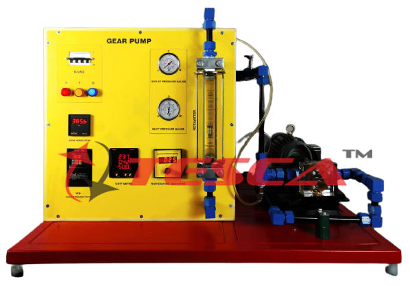
Gear pumps belong to the group of positive displacement pumps with a continuous flow. Two counter-rotating gears transport the medium from the intake side to the delivery side. The transported medium is between the housing and the tooth spaces. The pulsation-free flow increases linearly with speed. These pumps are particularly suitable for the generation of medium-high pressure at low flow rates. The experimental unit provides the basic experiments to get to know the operating behavior and the most important characteristic variables of gear pumps.
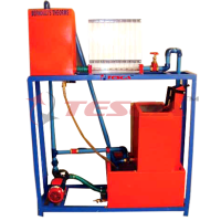
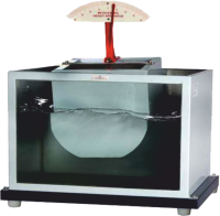
Tesca Gear Pump Test Apparatus features a closed circuit with a tank and a gear pump with variable speed via a frequency converter. The pump gears are mounted in a transparent housing and can be observed during operation. Flow rate and head are adjusted via a needle valve and an overflow valve. Oil is used as the medium.
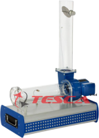
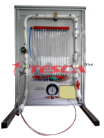
The experimental unit is fitted with sensors for pressure and temperature. The oval wheel meter
is especially used for the accurate flow measurement of viscous liquids. Oval wheel meters operate on the positive displacement principle with two precise oval gear wheels.
The microprocessor-based measuring technique is well protected in the housing. All the advantages of software-supported experiments and evaluation are offered by the software and the microprocessor. The connection to a PC is made by USB.
The well-structured instructional material sets out the fundamentals and provides a step-by- step guide through the experiments.
Specifications:
Functioning and operating behavior of a gear pump
Closed oil circuit contains a gear pump with variable speed via frequency converter and a transparent tank
Transparent housing for observing the pump gears
Needle valve for adjusting the flow rate
Overflow valve for adjusting the head
Sensors for temperature and pressure on the intake and delivery side of the pump
Oval wheel meter as a flow sensor
Microprocessor-based measuring technique
Optional unit-specific software for data acquisition and operation via USB under Windows Vista or Windows 7
Technical Specifications:
Gear pump with speed-controlled drive
Power consumption: 370W
Nominal speed: 200...1000min-1
Max. flow rate: approx. 15cmÑ per revolution
Max. head: approx. 100m Overflow valve: 0...5,5bar Measuring ranges
Pressure (intake side): -1...1bar
Pressure (delivery side): 0...5bar
Flow rate: 0...25L/min
Temperature: 0...100°C
Optionally available:
Gear pump (motor - pump), computer controlled:
Maximum flow: 15 l./min.
Maximum height (approx.): 50 MW (meter of water column).
Electric AC motor:
0.5 HP (horsepower).
- 0 to 1400 rpm.
The pump velocity is adjustable with a frequency inverter, controlled by the computer (PC). Sensors:
Discharge pressure sensor: from 0 to 6.2 bar.
Admission Pressure sensor: from -1 to 0 bar.
Flow sensor: from 0 to 15 l./min.
By the previous sensors we can make the measurement of the most typical parameters of the pump:
Speed motor.
Torque.
Total impelled flow.
The admission and discharge pressure.
Calculated values:
Total height.
Hydraulic power.
Mechanic power.
Efficiency.
Flow control valve.
Transparent water tank, capacity: 40 l.
Optional:
‘Sci-Cal’ Computer Control Software
PID Computer Control + Data Acquisition + Data Management.
Compatible with actual Windows operating systems. Graphic and intuitive simulation of the process on a screen.
Compatible with the industry standards.
Registration and visualization of all process variables in an automatic and simultaneous way.
Flexible, open, and multi-control software, developed with actual windows graphic systems, acting simultaneously on all process parameters.
Analog and digital PID control.
Menu for PID and setpoint selection required in the whole work range.
Management, processing, comparison, and storage of data.
Sampling velocity up to 250 KS/s (Kilo samples per second).
Calibration system for the sensors involved in the process.
It allows the registration of the alarm state and the graphic representation in real-time.
Comparative analysis of the obtained data, after the process and modification of the conditions during the process.
Open software, allowing the teacher to modify texts, instructions. Teacher’s and student’s passwords to facilitate the teacher’s control on the student, and allowing the access to different work levels.
This unit allows the 30 students of the classroom to visualize simultaneously all results and manipulation of the unit, during the process, by using a projector or an electronic whiteboard.
This module requires Control Interface Module and Data Acquisition.
Interface In-built Module:
This control interface is common for the ‘Tesca’ trainers and can work with one or several trainers.
The Control Interface is part of the SCADA system.
Control interface with process diagram on the
Experiments:
Principle of operation of a gear pump
Recording of pump characteristics
Relationship between head and speed
Effect of pressure limitation
Determination of efficiencies
front panel.
Services Required:
The unit control elements are permanently computer-controlled.
Simultaneous visualization in the computer of all parameters involved in the process.
Calibration of all sensors involved in the process.
Real-time curves representation about system responses.
All the actuators’ values can be changed at any time from the keyboard allowing the analysis of curves and responses of the whole process.
Shield and filtered signals to avoid external interferences.
Real-time PID control with flexibility of modifications from the computer keyboard of the PID parameters, at any moment during the process.
Real-time PID control for parameters involved in the process simultaneously.
Proportional control, integral control, and derivative control, based on the real PID mathematical formula, by changing the values, at any time, of the three control constants (proportional, integral, and derivative constants).
Open control allowing modifications, at any moment and in real-time, of parameters involved in the process simultaneously.
Three safety levels, one mechanical in the unit, another electronic in the control interface, and the third one in the control software.
Mains power supply: 220-240V, 1Ph, 50Hz
Enquiry Form
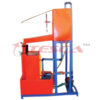
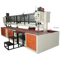
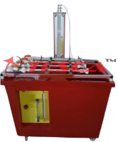
Related Product
Tesca specialize in doing turnkey projects that is fully operable when it is handed over to the project authority. Starting from inception to application training, Tesca provides the services as ONE source solution. Working side by side with government authorities and people across the World, we help countries to perform better. We support countries grow their economies, strengthen their education and health systems and improve financial management. We do this by providing consultancy & training in environment safety, education, health strengthening.
Category
Useful Links
Contact Us
International Sales:
 91-9829132777
91-9413330765
India Sales:
91-9588842361
2025 © All Rights Reserved.