Forces In Various Single Plane Trusses
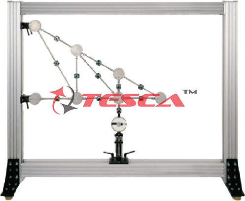
Order Code: 32148
Category: Strength of Materials Lab
Features Measurement of the bar forces in a single plane truss Construction of various truss forms Bars with strain gauge full bridges to measure bar force Computerized evaluation of experiments The object of the experiment ...
SPECIFICATION
Features
- Measurement of the bar forces in a single plane truss
- Construction of various truss forms
- Bars with strain gauge full bridges to measure bar force
- Computerized evaluation of experiments
- The object of the experiment is to measure the bar forces in a single-plane truss subjected to a single external force.
Tesca Forces in Various Single Plane Trusses Trainer set-up features bars with special snap-lock closures on their ends allowing them to be fixed easily into the node disc. The range of different bar lengths provided permits three forms of truss to be constructed.
The bars are hinged, joined together by node discs, and are subjected only to compressive or tensile stress. No moments are transmitted in the nodes; they can be regarded as frictionless. Consequently, our trusses can be considered ideal trusses. A load application device attached to a node disc generates an external force. All the forces on the truss bars are recorded by means of strain gauges.
Computerized evaluation is provided by a measurement amplifier (16 input channels). If there are more than 16 measuring points, the measurement amplifier can be extended by a measuring point add-on unit to 32 input channels. The software is used to manage the measurement data and provide a graphical representation of the bar forces. The software features a comprehensive help function.
All the component elements of the experiment are clearly laid-out and housed securely in a storage system. The complete experimental set-up is arranged in the highly stable anodized aluminum frame.
The well-structured instructional material sets out the fundamentals and provides a step-by-step guide through the experiments.
Specifications
Investigation of bar forces in a statically determinate truss
Construction of various trusses possible
2 supports with node discs
Load application device with force gauge mountable on different node discs
Strain gauge to measure the force on each bar
Measurement amplifier required
Software to evaluate measurement data
Storage system to house the components
Experimental set-up in frame
Technical Specifications
Bars: 19
- 2 bars 150mm
- 5 bars 259mm
- 7 bars 300mm
- 1 bar 397mm
- 3 bars 424mm
- 1 bar 520mm
- Angle between bars: 30°, 45°, 60°, 90°
- Maximum bar force: 500N
- Strain gauge on each bar
- Height of truss max. 450mm
- Length of truss max. 900mm
Load application device
- 500...+500N
- Graduations: 10N
Experiments
Measurement of the bar forces in various single-plane trusses
Dependency on the external force
- Magnitude
- Direction
- Point of application
Comparison of measurement results with mathematical methods
- Method of joints
- Ritter’s method of sections
Basic principle: measurement of forces using strain gauges
Scope of Delivery
- 1 set of bars
- 5 node discs
- 2 supports with node disc
- 1 load application device
- 1 set of cables
- 1 storage system with foam inlay
- 1 software CD
- 1 set of instructional material


 91-9829132777