Dynamic Behavior Multistage Spur Gears
Order Code: 32147
Category: Strength of Materials Lab
Features Single-stage, two-stage, or three-stage spur gear with distributed rotational inertia Drive via cable drum and variable set of weights Inductive speed sensors on all shafts Software for data acquisition Gears...
SPECIFICATION
Features
- Single-stage, two-stage, or three-stage spur gear with distributed rotational inertia
- Drive via cable drum and variable set of weights
- Inductive speed sensors on all shafts
- Software for data acquisition
Gears are employed as a link between the drive machine and the work machine. They are used to vary torque and speed and to change direction. The aim of dynamic gear analysis is an understanding of the motion sequences and the influence of inertia.
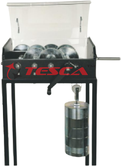
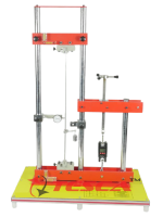
The trainer includes four parallel shafts, three drive wheels, and three drive gears. Coupling pins can be used to couple the shafts such that different gear stages can be realized. A flywheel may be attached to each shaft in order to increase the rotational inertia. The gear is accelerated via a cable drum and a variable set of weights. The set of weights is raised via a crank. A ratchet prevents the weight from accidentally escaping. A clamping roller freewheel enables free further rotation after the weight has been released. A hand brake allows smooth deceleration. The transparent protective cover with a safety lock prevents accidental contact with the rotating parts.
Inductive speed sensors on all drive gears allow the rotational speeds to be measured. The measured values are transmitted directly to a PC via USB. The data acquisition software is included. The angular acceleration can be read from the diagrams.
The well-structured instructional material sets out the fundamentals and provides a step-by-step guide through the experiments.
Tesca Dynamic Behaviour of Multistage Spur Gears unit is used to study the dynamic behavior in single-stage, two-stage, and three-stage spur gears during transient operation.
Specifications
Investigation of the dynamic behavior of 1-stage, 2-stage, or 3-stage spur gears
4 shafts, 3 drive wheels, and 3 drive gears
Shafts can be coupled by coupling pins
Optional attachable flywheels to increase the rotational inertia on each shaft
Gear is accelerated via cable drum and variable set of weights
Weight raised by a hand crank; ratchet prevents accidental release
Clamping roller freewheel enables free further rotation after the weight has been released
Gear decelerated via hand-operated brake
Transparent protective cover with safety lock and protective grill for the set of weights
Inductive speed sensors on all drive-gears
Software for data capture via USB under Windows Vista or Windows 7
Technical Specifications
3-stage gear with 4 shafts
- Transmission ratio per stage: i = 4:1
- Overall transmission ratio: i = 64:1
Gear width: 16mm, module 2mm Drive
- Set of weights: 5...50kg
- Drop height: max. 0,65m
- Max. potential energy: 320Nm
Measuring range
- Speed: 0...2.000min-1
Experiments
Determining the angular acceleration on gears
Determining the mass moment of inertia of the gear
Determining the friction
Determining the gear efficiency
Scope of Delivery
- 1 trainer
- 1 set of weights
- 1 CD with software + USB cable
- 1 set of instructional material



 91-9829132777