Building Automation In Heating & Air - Conditioning
Order Code: 32436
Category: Refrigeration & Air Conditioning Lab
Heating and air conditioning technology is a key topic in building services engineering. For the control and monitoring of heating and air conditioning systems PLC air conditioning controllers are usually used in building services engineering. The co
SPECIFICATION
Features
- Operation and programming of a DDC for heating and air conditioning systems1
- Simulated heating system with water heating1
- Simulated air conditioning system with outer air and recirculating operation
Heating and air conditioning technology is a key topic in building services engineering. For the control and monitoring of heating and air conditioning systems PLC air conditioning controllers are usually used in building services engineering. The controller is adjusted to the respective tasks by programming, making additional cabling unnecessary.
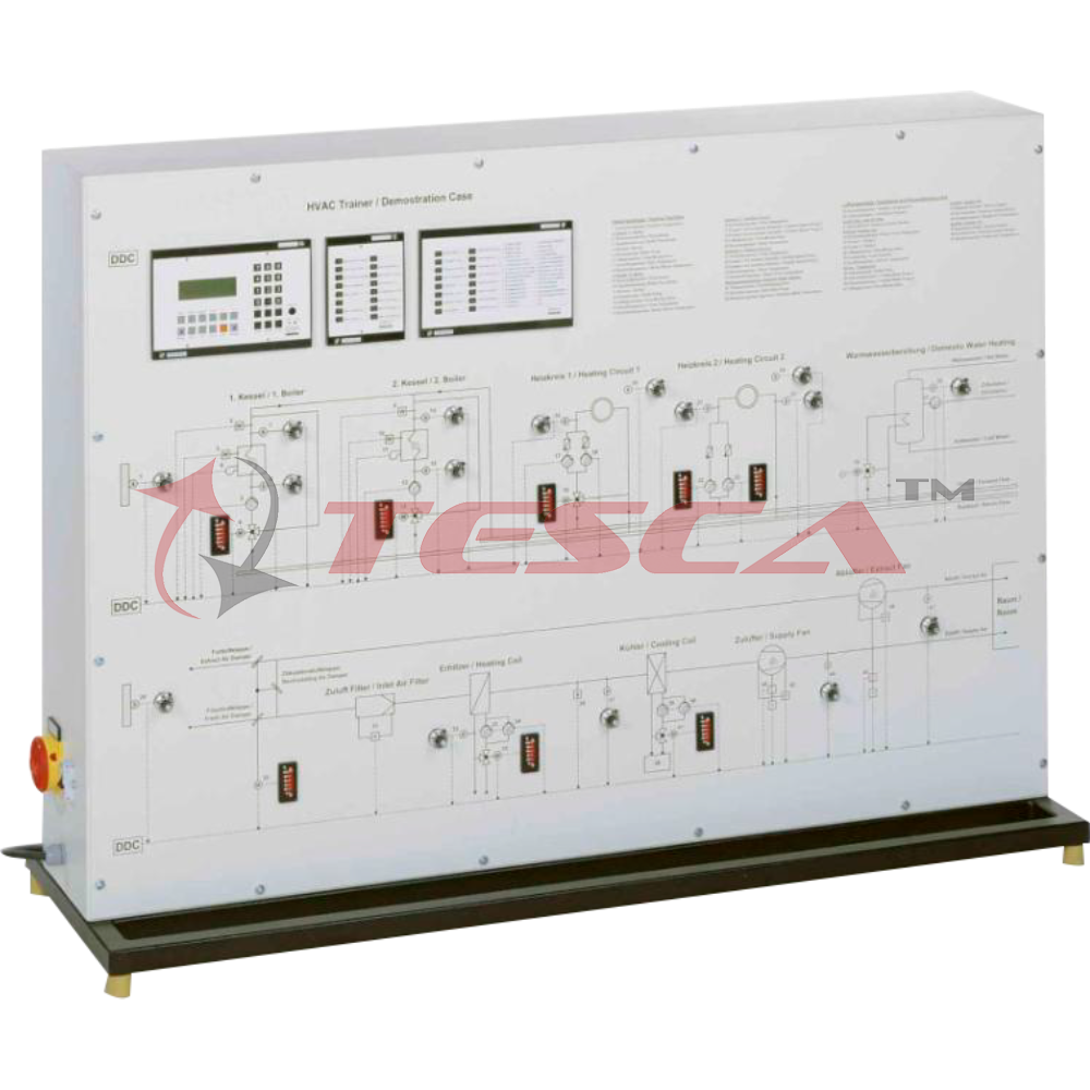
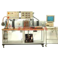
In the Tesca Building Automation in Heating & Air-Conditioning Systems trainer 32436, the operation and programming of a PLC for a heating and air conditioning system can be learned. The process schematics for the two simulated systems are shown on the front panel.
The simulated heating system has two boilers connected in parallel. The feed flow temperature is controlled through the outside temperature using 3-way mixing valves. There are two heating lines with simulated heaters and different actuators: 3-way mixing valves and pumps. An additional 3-way mixing valve is the actuator for water heating.
The simulated air conditioning system with air heater, air cooler and fans can be operated in outer air and recirculated operation via flaps with a motor as actuator.
Both process schematics contain potentiometers simulating e.g. a change in the outside, room or feed flow temperature. Bar-graph displays and lamps indicate the operating states of the actuators.
In addition to manual configuration and parameterization via buttons, the PLC can also be adjusted for the respective control task using the configuration software supplied. It further enables the monitoring of safety devices such as a low water cut-off in the boiler. The simulation of faults, such as triggering the differential pressure switch at the fan, can be carried out via buttons.
The well-structured instructional material sets out the fundamentals and provides a step-by-step guide through the experiments.
Specifications
- Experimental unit from the Tesca for the training of mechatronics engineers for refrigeration
- Operation and programming of a PLC for heating and air conditioning systems
- Process schematic of the simulated heating system with 2 boilers, 2 heating lines and water heating
- Process schematic of the simulated air conditioning system with selectable outer air and recirculating operation
- Programmable PLC with selection and display of the operating states and error simulation
- Process schematics with bar-graph displays and lamps for operating states of the actuators
- 16 potentiometers in the process schematics to adjust simulated temperatures
- Process schematics on the front panel
Technical Specifications
- PLC
- 16 Digital inputs
- 8 Digital outputs
- 16 Analogue inputs
- 8 Analogue outputs
- Control circuits: 4
- PLC functions
- Auxiliary energy: 24VAC
- 14 buttons to select the operating states
- 16 buttons for error simulation
- Bar-graph display measuring range: 0...100%
Experiments
- Operation and programming of a PLC
- Effects of temperature changes on the operating behavior of a
- Heating system
- Air conditioning system
- Fault finding in a
- Heating system
- Air conditioning system
- Safety devices
Requirements
220 – 240V, 50Hz, 1 phase Power Supply




 91-9829132777