1KW Rankine Cycle Steam Turbine
Order Code: 32460
Category: Boiler & Steam Generators
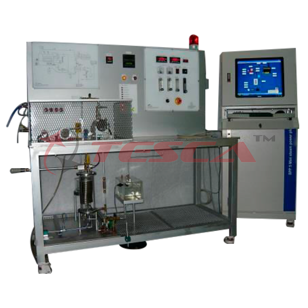
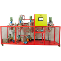
Tesca Rankine Cycle Steam Turbine 32460 is used to drive bulb loads or for heating system. Steam generators and steam consumers together form a steam power plant. Steam power plants work according to the Rankine cycle which is still one of the most i
SPECIFICATION
Features
- Laboratory-scale steam generator for wet or overheated steam
- Characteristic values of a steam boiler
- Various safety and monitoring devices
- Setting up a complete steam power plant in conjunction with the steam turbine
Tesca Rankine Cycle Steam Turbine 32460 is used to drive bulb loads or for heating system. Steam generators and steam consumers together form a steam power plant. Steam power plants work according to the Rankine cycle which is still one of the most important industrially used cyclic processes. Steam power plants are mainly used for electrical power generation.
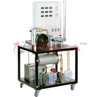
The steam generator and the axial steam turbine together form a complete laboratory-scale steam power plant.
The trainer serves to familiarize students with the components and principle of operation of a steam generator and enables them to examine the characteristic values of the system. The numerous safety devices of the steam generator can be tested and checked using various monitoring devices.
If the steam generator is operated without the steam turbine, the generated steam is directly liquefied in a condenser and fed back into the evaporation circuit via a tank.
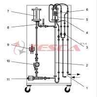
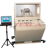
As all components are clearly arranged on the front panel, the cyclic process can be easily monitored and understood. Sensors record the temperature, pressure and flow rate at all relevant points. The measured values can be read on digital displays. At the same time, the measured values can also be transmitted directly to a PC via USB. Optionally the data acquisition software DAQ or SCADA can be included.
The steam generator has been constructed according to the Technical Regulations for Steam, pressure-tested and is equipped with all legally required safety devices.
Shown below is an example model of a steam turbine system based on the Rankine Cycle. The cycle includes superheating and reheating to prevent condensation at the high-pressure turbine and the low-pressure turbine, respectively. The cycle also has regeneration by passing extracted steam through closed feedwater heaters to warm up the water and improve cycle efficiency. The Saturated Fluid Chamber block models a separate saturated liquid volume and saturated vapor volume and is used to create the boiler and the condenser
Simulation Results from Logging
This plot shows the energy exchanges in the system. Heat from the furnace is added by the boiler, the superheater, and the reheater. Useful work is extracted from the steam by the high-pressure turbine (HPT) and the low-pressure turbine (LPT). Waste heat is rejected to the coolant in the condenser. Heat is also transferred from the extracted steam to the feedwater to improve thermal efficiency.
This plot shows the mass through rates through the system. A portion of the steam is extracted between the high-pressure turbine (HPT) and the low-pressure turbine (LPT). The extracted steam is used to warm up the feedwater before rejoining the main flow at the condenser. The flow rates of the main flow and the extracted steam are regulated by the controllers to maintain the liquid level in the boiler and the preheater condenser, respectively
Specifications
1) Boiler: Independently certified electric boiler with manual control, pressure switches, safe pressure
cut out and large capacity relief valve
Capacity 20 liters
Steam Pressure 8 kg/cm2
Standards Non IBR
Operation Electrical heaters
2) Turbine: Single stage, axial flow impulse (De Laval) turbine on a vertical shaft mounted in
corrosion resistant sealed ball bearings.
Construction Convergent-divergent nozzle discharges at 20 to plane of turbine rotation and rotor has
blades with 45 inlet and discharge angles.
Rotor diameter 50mm.
Maximum turbine speed 3,000 rpm.
Capacity 1 KW Max
Impeller inner diameter 54mm
Max. inlet pressure 8 bar abs.
Max. outlet pressure 1bar abs.
3) Water cooled Condenser:
Condenses turbine exhaust steam allowing heat rejection from the system to be measured.
Construction Coil tube type
Operating Pressure 2 kg/cm2 max
4) Feed Water Reservoir:
Collects condensate from the condenser for return via the feed pump to the boiler.
5) Feed Pump: low volume flow pump.
Flow rate 500 LPH
6) Flow Meters:
For condenser cooling water. Allows measurement of heat rejection from the condenser.
Flow Rate 10 -1000 lph
Output 4-20 mA
Programmable Circuits for Calibrations of the Flow meters
7) Digital Thermometer
0.1ºC resolution, with multi-way selector switch for all relevant temperatures
Type Pt 100
Range 0-600 deg C
8) Pressure Sensors
Range 0-16 bar
Output 4-20 mA
9) Turbine load Digital indicator in Watts
10) Measuring ranges
1) Pressure
steam inlet: 0…16bar
condenser: 0…1,6bar
differential pressure: 0…50mbar
2) Cooling water flow rate: 0…720L/h
3) Speed: 0…3000 min-1
4) Load: 0…1000 Watts
5) Temperature: 0…400°C
Piping In S.S and Copper as per suitable application in the System
Experiment Capabilities
- Investigation of a true Rankine Cycle Steam plant.
- Determine of cycle thermal efficiency based on shaft power.
- Determination of friction losses at various exhaust pressures.
- Investigation of turbine torque/speed and power/speed characteristics.
- Investigation of steam quality by throttling.
- With the optional power generation module demonstration of electrical power generation.
Services Required
- Electric Supply- 10 kW, 3 phase 440 V, 50Hz AC (Or optional 3 Phase, 220V, 60Hz AC) with proper earthing.
OR
- Optional: Input from PV Solar Cells or Wind Generated Power (Requires input from user to redesign the input option)
- Continuous supply of cold water (35-50 Liters/min) & drainage facility.
- Boiler feed water supply 5 liters/hour (10-15 Liters de-mineralized/distilled water for initial fill)



 91-9829132777