
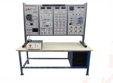
Power electronics training set
Order Code: 24257587.8
Category: General Lab Equipment V
Selenium rectifier Rated alternated voltage: 30 Vrms Rated continuous voltage: 24 Vav Rated continuous current: 10 Aav Group of diodes Direct average current: IFAV = 12 A Direct non repeti...
SPECIFICATION
Selenium rectifier
-
Rated alternated voltage: 30 Vrms
-
Rated continuous voltage: 24 Vav
-
Rated continuous current: 10 Aav
Group of diodes
-
Direct average current: IFAV = 12 A
-
Direct non repetitive overload current:
-
IFSM = 75 A (tp = 10 ms)
-
Repetitive peak reverse voltage: URRM = 1000 V
-
Recovery reverse time: trr = 65 ns max
Group of SCR
-
Direct average current: ITAV = 7.6 A max.
-
True RMS value of the direct current: ITRMS = 12 A
-
Max. repetitive reverse voltage: URRM = 800 V
-
Trigger current: IGT = 15 mA max.
-
Trigger voltage: UGT = 1.5 V max.
-
I2t = 72 A2s
Group of Triac
-
True RMS value of the direct current: ITAV = 8 A max.
-
Non-repetitive peak current:
ITSM = 70 A, 50Hz (77A, 60Hz) -
Max. repetitive reverse voltage: UDRM = 800 V
-
Trigger current: IGT = 25 mA max. (all the quadrants)
-
Trigger voltage: UGT = 2.5 V max.
-
State keeping current:
-
IH = 25 mA max.
-
I2t = 24 A2s
Group of MOSFET
-
Drain-source voltage: UDS = 400 V
-
Continuous drain current: ID = 10 A
-
Drain-source on-state resistance: RDS(on) = 0.55 Ω
-
Gate-source voltage: UGS = +-20 V
Group of IGBT
-
Collector?emitter voltage: UCES = 600 V
-
Continuous collector current: Ic = 24 A at Tc = 25ºC
-
Collector?emitter saturation voltage:
-
UCEsat = 1.8 Vtyp at Ic=15 A
-
Gate?emitter voltage: UGE = ± 20 V
Voltage Reference Generator.
-
Power supply: +15 V ; 0 V ; -15 V
-
Range of the continuous regulation reference signal:
from - 10 V to + 10 V, from 0 to + 10 V -
Range of the step reference signal:
from - 10 V to + 10 V, from 0 to + 10 V -
Switch for selecting between internal potentiometer reference signal and external reference signal
-
Switch for selecting between the 0 / ±10 V range and the 0 / +10 V range.
Trigger point limiter
-
Stability limit for rectifier: 0° to 180°
-
Stability limit for inverter: 180° to 0°
-
Power supply: +15 V / 0 V / - 15 V
Two pulse control unit.
-
Power supply: +15V/ 0V / - 15V (25mA)
-
Synchronization voltage: 1 to 440 V
-
Control voltage Uc: 0 V to 10 V
-
Trigger angle: 180° to 0°
-
Number of outputs: 2 x 2
-
Possibility of pulse train or single pulse.
-
Possibility of selecting two natural switching points: 0° and 30°.
-
Inhibit voltage:
UINH = 15 V (open): trigger pulses.
UINH = 0 V: no trigger pulses
Six pulse control unit
-
Power supply: +15V/0V/? 15V (300mA)
-
Synchronization voltage: 1 to 440 V
-
Analogue control voltage Uc: 0 to 10V
-
Digital TTL control: DWH = FH...FFH (15...255)10
-
Trigger angle: 180° to 0°(300°...120°/60°...240°)
-
Number of outputs: 3 x 2
-
Possibility of pulse train or single pulse.
-
Possibility of excluding the secondary pulse.
-
Possibility of selecting three natural switching points: 0°, 30° and 60°.
-
Inhibit voltage:
UINH = 15 V (open): trigger pulses
UINH = 0 V: no trigger pulses
PWM, PFM, TPC control unit
-
Power supply: +15V/0V/? 15V (600 mA)
-
Control voltage: Uc: 0 to 10V
-
PWM: 20?200 Hz/0.2?2 kHz/2?20 kHz
-
Duty cycle D = ton/T = 0?0.95
-
PFM: 5?50 ms/50?500 ms/0.5?5 s
-
Frequency: 20 Hz to 20 kHz
-
TPC: Hysteresis: UH = 0 to 2 V
-
Number of outputs: 2 x 2, with led indication of the status
-
Output amplifier: threshold voltage 5 V, short?circuit proof
Inhibit voltage:
UINH = 15 V (open): trigger pulses.
UINH = 0 V: longer pulses at certain outputs only
Run-up control unit
-
Power supply: -15 V/0 V/ 15 V
-
Input signal range: Ui = -10 V ... 10 V
-
Fine adjustment of the slew-rate:0.5 . . . 50 V/s
-
Fine adjustment of the voltage gain:0.1 . . . 1
-
Inhibit voltage:
-
UINH = 0 V: zero output voltage
-
UINH = 15 V
-
UINH = 15 V (open): output voltage U0 runs up and output UINH = 0 V
PID Controller
-
Power supply: +15 V ; 0 V ; -15 V
-
Input summing node for two different reference variables UR and
UC and for one controlled variable UA. -
Signal voltage range: -10V .... +10V
-
Parameters of the controller continuously adjustable
-
Proportional gain: Kp = 0 ... 1000
-
Time of the integral action: TI = 1ms ... 100s
-
Time of the derivative action: TD = 0.2ms ... 20s
-
Reset input of the integral controller.
-
Output summing node to add or subtract noise variables.
-
Measurement terminal for the error signal
-
Adjustment screw for the output offset.
-
Three led indicators of the sense of deviation.
-
Coarse and fine adjustment of the proportional gain Kp, of the
time of the integral action TI and of the time of the derivative action TD. -
Indicator of over-range: led "over" on when the output voltage is higher than 10 V or lower than -10 V.
-
Input Ioff for resetting the I controller
Absolute value generator
-
Power supply: -15 V/0 V/+15 V
-
Input signal range Ui: -10 V . . . + 10 V
-
Adjustable gain: 0 . . . 1
-
Inverting control input
-
UINV = 0 V: the input signal is inverted
-
UINV = 15 V or disconnected: the input signal is not inverted
-
Inhibit voltage:
-
UINH = 0 V: the output signal is zero
-
UINH = 15 V (open): the absolute value circuit is active
-
Gain and Offset Adjust
-
Power supply: +15 V; 0 V ; -15 V
-
Voltage interval of the input signal: -50 V, ..., +50 V
-
Adjustable level through the setting of the gain: 0 ....1, 0.... 10, 0.... 100
-
Attenuation of the pulse signals.
-
Time constants: 0,1 .... 10 ms; 10.... 100 ms
-
Offset voltages that can be connected: -10 V.... +10 V
-
Coarse setting through rotary switches.
-
Potentiometer fine setting
Mains transformers
-
Power supply: three?phase from mains
-
Protection through three?pole magneto?thermal switch
Capacitors
-
Rated value: 2 x 1000 μF
-
Rated voltage: 385 V
-
Protection against polarity inversion.
-
Discharge resistance: 330 kΩ (t = 330 s
Super-fast fuses.
-
Nominal voltage: 660 Vac
-
Nominal current: 3 x 6.3 A , 3 x 10 A
Switching transformer
-
Ferrite core N27 without air gap.
-
Primary: 2 x 115 V, 2 x 48 turns
-
Thermal protection: 2 x 0.6 A
-
Secondary: 2 x 15 V/ 4.5 A, 2 x 7 turns
-
Inter-winding shield.
-
Rated power: 135 VA
-
Rated frequency: 15 kHz
Trigger pulse switch
-
Two pulse inputs.
-
Two control inputs.
-
Eight electrically isolated pulse outputs.
-
Power supply: +15 V
Switching logic
-
Input Xn for torque comparator (speed set point value).
-
Input Xi for current comparator with adjustable limit threshold.
-
Output SA and SB for the corresponding inputs of the
-
Trigger pulse switch with led indication of the active converter.
-
Output INV for the corresponding inverting input of the absolute value generator.
-
Output INH for the corresponding inhibit input of the two
-
pulse control unit, with adjustable delay time from 10 ms to 2 s and led indication of the commutating time.
-
Current comparator output C for EXT selection input of the active elements of the adaptive PI controller.
-
Power supply: +15 V/0 V/?15 V
Phase control fault simulator
-
Power supply: 110 to 230 V, 47-63 Hz
-
Ohmic load: 1.2 kW max
-
Isolation amplifier
-
Isolation amplifier, channels A, B, C, E:
-
Frequency range: dc to 80 kHz.
-
Input voltage (between 0 and U)
-
Max 620 Vdc/460 Vac
-
Input resistance Ri = 1 MW in all ranges
-
Three?stage attenuator: MT = 1: 1; 1/10; 1/100
-
Accuracy: ±2% of full scale range Input current (between 0 and I)
-
Max: 10 A continuous; 16 A for t< 15 min; 20 A for t<2 min.
-
Internal resistance: 30 mw in all ranges
-
Two?stage attenuator: MT = 1 V/A; 1/3 V/A
-
Accuracy: ±5% of full scale range
-
Five outputs: A, B, C, D, E with led for over range indication
-
Output resistance RO: 100 W
Multiplexer:
-
Mux channels, selectable: 1 to 8 (4 x signal; 4 x zero line)
-
Gain attenuator, adjustable: 0.2 to 1.
-
Y?position, adjustable: ?8 V to + 8 V.
-
Trigger source, switchable to A, B, C, D, E.
-
Mux frequency, adjustable: 50 kHz to 500 kHz (typical).
-
Two BNC outputs for oscilloscope
Mathematical module and filter:
-
Functional modes for channel D: Addition A+B; subtraction A?B; multiplication AxB/10 or AxB; reconstruction of the phase voltage LIN (A, B, C) from the line?to line voltages; channel E switched into channel D for multiplexing.
Filter
-
Low pass active filter of the 2° order required for the recovery
of the fundamental wave out of the PWM signals. -
Cut?off frequency: 1 kHz.
-
Space vector indicator
-
Voltage vector: indication with 7 led.
-
Magnetic flux vector: BNC outputs X e Y for oscilloscope
-
Power supply.
-
Single?phase from mains Frequency: 50/60 Hz
Support with 3 shunts 1 ohm.
-
Resistance: 1 Ω
-
Accuracy: ± 1%
-
Max. current: 2.5A
Support with 3 shunts 0.1 ohm
-
Technical features:
-
Resistance: 0.1 Ω
-
Accuracy: ± 1%
-
Max. current: 8 A
Frequency converter
-
Output voltage: 3 x 0...230 V
-
Output current: 3 x 8 A max.
-
Supply voltages:
-
Power circuit, 1 x 255 V max, 50/60 Hz control circuit,
-
Single?phase from mains
PWM Control Unit
-
Control unit used in conjunction with the frequency converter to build a voltage?source inverter which operates with PWM control.
-
All of the control, monitoring and measuring functions
are integrated into the control unit (a microcontroller implements the management via a program stored in
EPROM) while the frequency converter contains solely
the power components. -
A PWM modulator controls the power transistors of the inverter and thus generates a sine?shaped motor current.
-
Modulation possibilities: PWM, VVC, trapezium shaped and
Enquiry Form
Related Product


Tesca specialize in doing turnkey projects that is fully operable when it is handed over to the project authority. Starting from inception to application training, Tesca provides the services as ONE source solution. Working side by side with government authorities and people across the World, we help countries to perform better. We support countries grow their economies, strengthen their education and health systems and improve financial management. We do this by providing consultancy & training in environment safety, education, health strengthening.
Category
Useful Links
Contact Us
International Sales:
 91-9829132777
91-9413330765
India Sales:
91-9588842361
2025 © All Rights Reserved.