Table of Contents
Resistors are special components with a specific electrical resistance that can be used to limit the flow of current through a circuit. As passive components that can only consume power and not generate it, resistors are great for limiting current, dividing voltages and more. By using resistors, it becomes possible to control the amount of current and voltage in a circuit, thus controlling the circuit overall.
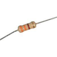
Because the primary purpose of a resistor is to limit the flow of electrical current, the key parameter of resistors is their resistance value. As such, resistors are usually named based on their ohm (Ω) rating and can be identified by different colored bands.
The formula for resistance is given as: R = V/I
and for a material of length l, cross-section area A and specific resistivity ρ ;
Classification of resistors
- Low Resistance: Resistance having value 1Ω or below are kept under this category.
- Medium Resistance: This category includes Resistance from 1Ω to 0.1 MΩ.
- High Resistance: Resistance of the order of 0.1 MΩ and above is classified as High resistance.
Types of resistors:
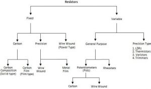
Carbon resistor is one of the most common types of electronics used. They are made from a solid cylindrical resistive element with embedded wire leads or metal end caps. Carbon resistors come in different physical sizes with power dissipation limits commonly from 1 watt down to 1/8 watt.
Film Resistor is a general term referring to different types such as Carbon Film, Metal Film, and Metal Oxide Film resistors. They are generally manufactured by depositing pure metals (e.g., nickel) or oxide film (e.g., tin-oxide) onto an insulating ceramic or substrate.
Wirewound resistor are passive electrical devices that limit or restrict current flow in a circuit. The conductive wire can be made of varying alloys and thickness to control the resistance value. Wirewound resistors are typically used in high power and industrial applications such as circuit breakers and fuses.
Resistor Color Code
Small resistors use coloured painted bands to indicate both their resistive value and their tolerance with the physical size of the resistor indicating its wattage rating. These coloured painted bands produce a system of identification generally known as a Resistors Colour Code. An international and universally accepted resistor colour code scheme was developed many years ago as a simple and quick way of identifying a resistors ohmic value no matter what its size or condition. It consists of a set of individual coloured rings or bands in spectral order representing each digit of the resistors value. The resistor colour code markings are always read one band at a time starting from the left to the right, with the larger width tolerance band oriented to the right side indicating its tolerance. By matching the colour of the first band with its associated number in the digit column of the colour chart below the first digit is identified and this represents the first digit of the resistance value.


