Table of Contents
An operational amplifier, also known as op-amp or simply opamp, is a DC-coupled high-gain electronic voltage amplifier with a differential input and, usually, a single-ended output. In this configuration, an op amp produces an output potential (relative to circuit ground) that is typically 100,000 times larger than the potential difference between its input terminals. Operational amplifiers had their origins in analog computers, where they were used to perform mathematical operations in many linear, non-linear, and frequency-dependent circuits.
Op amps are among the most widely used electronic devices today, being used in a vast array of consumer, industrial, and scientific devices. Many standard IC op amps cost only a few cents in moderate production volume; however, some integrated or hybrid operational amplifiers with special performance specifications may cost over US$100 in small quantities. Op amps may be packaged as components or used as elements of more complex integrated circuits.
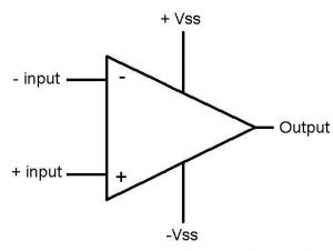
Characteristics of an ideal Op-amp
- An ideal op amp is usually considered to have the following characteristics:
- Infinite open-loop gain G = vout / vin
- Infinite input impedance Rin, and so zero input current
- Zero input offset voltage
- Infinite output voltage range
- Infinite bandwidth with zero phase shift and infinite slew rate
- Zero output impedance Rout
- Zero noise
- Infinite common-mode rejection ratio (CMRR)
- Infinite power supply rejection ratio
Real op-amps differ from the ideal model in various aspects.
Basic Applications of Op-amp
-
Inverting Apmlifier
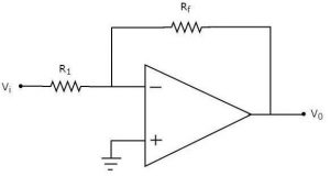
An inverting amplifier, also known as an inverting operational amplifier or an inverting op-amp, is a type of operational amplifier circuit which produces an output which is out of phase with respect to its input by 180 degree.
This means that if the input pulse is positive, then the output pulse will be negative and vice versa. The figure below shows an inverting operational amplifier built by using an op-amp and two resistors. Here we apply the input signal to the inverting terminal of the op-amp via the resistor Ri. We connect the non-inverting terminal to ground. Further, we provide the feedback necessary to stabilize the circuit, and hence to control the output, through a feedback resistor Rf.
Inverting amplifiers exhibit excellent linear characteristics which make them ideal as DC amplifiers. Moreover, they are often used to convert input current to the output voltage in the form of Transresistance or Transimpedance Amplifiers. Further, these can also be used in audio mixers when used in the form of Summing Amplifiers.
-
Non-Inverting Amplifier
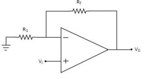
A non-inverting amplifier takes the input through its non-inverting terminal, and produces its amplified version as the output. As the name suggests, this amplifier just amplifies the input, without inverting or changing the sign of the output. When we apply any signal to the non – inverting input of, it does not change its polarity when it gets amplified at the output terminal. So, in this case, the gain of the amplifier is always positive.
-
Differentiator and Integrator
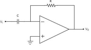
An op amp differentiator is basically an inverting amplifier with a capacitor of suitable value at its input terminal. The figure below shows the basic circuit diagram of an op amp differentiator.
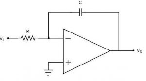
An op-amp based integrator produces an output, which is an integral of the input voltage applied to its inverting terminal. The circuit diagram of an op-amp based integrator is shown below
-
Adder / Summing Amplifier
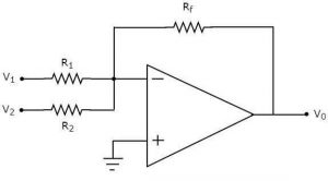
An adder, also known as summer, is an electronic circuit that produces an output, which is equal to the sum of the applied inputs. This section discusses about the op-amp based adder circuit. An op-amp based adder produces an output equal to the sum of the input voltages applied at its inverting terminal. It is also called as a summing amplifier, since the output is an amplified one
-
Subtractor
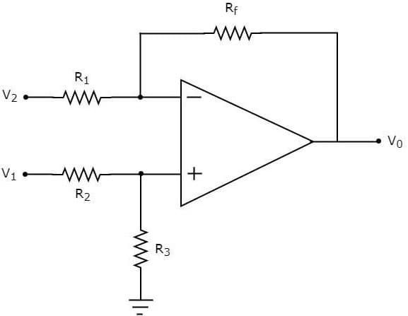
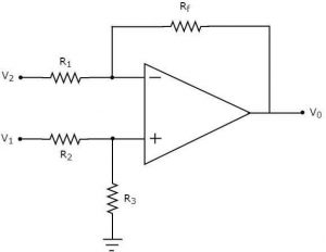
A difference amplifier or op amp subtractor is a specially designed op amp based amplifier circuit, which amplifies the difference between two input signals and rejects any signals common to both inputs. An op-amp based subtractor produces an output equal to the difference of the input voltages applied at its inverting and non-inverting terminals. It is also called as a difference amplifier, since the output is an amplified one.
Operational amplifiers are particularly versatile circuit blocks. They find applications in a host of different circuits where their attributes of high gain, high input impedance low output impedance and a differential input enable them to provide a high performance circuit with a minimum of components. By using negative, and sometimes positive feedback around the op amp chip they can be used in many applications and circuits to provide a variety of different functions from amplifiers and filters to oscillators, integrators and many other functions. There are many op amp circuits that cover most of the main analogue functions that are needed. As a result of this, operational amplifiers have become the workhorse of the analogue electronics designer. Apart from the circuits discussed above opamp is also used as converters of electrical quantities, comparators, log & anti-log amplifiers, rectifiers, clippers, clampers, active filters, sinusoidal oscillators, waveform generators.


