Table of Contents
“The DE Sauty bridge is a type of bridge circuit used to measure the impedance of electrical components or systems”. It consists of four branches, each containing a resistor and a reactive component (either an inductor or capacitor). The reactive component in one branch is connected in parallel with the resistor in another branch, and the reactive component in the third branch is connected in series with the resistor in the fourth branch.
The oscillator generates an alternating current (AC) signal, which is applied to the bridge. The detector, which is usually a meter, measures the voltage across the bridge. By adjusting the values of the resistors and reactive components, the bridge can be balanced, meaning the voltage across the bridge is zero. When the bridge is balanced, the impedance of the unknown component can be calculated from the known values of the resistors and reactive components in the bridge.
Uses, Components, Types and setup of DE Sauty Bridge with Oscillator and Detector Trainer Board
The DE Sauty bridge is named after its inventor, French engineer Paul DE Sauty. It is often used to measure the impedance of capacitors, inductors, and other types of passive electrical components, as well as the impedance of transmission lines and other electrical systems. Let’s read about DE Sauty Bridge uses, working principles and components etc.
What is DE Sauty Bridge With Oscillator and Detector Trainer Board?
“A DE Sauty bridge with oscillator and detector trainer board is a type of educational equipment used to teach students about the DE Sauty bridge circuit and its uses.” It typically consists of a circuit board with all the components needed to build a DE Sauty bridge, including resistors, inductors, and capacitors, as well as an oscillator and a detector (usually a meter).
The trainer board allows students to build and experiment with the DE Sauty bridge circuit in a controlled, hands-on environment. It may also include a set of instructions or a manual that explains how to use the board and how to interpret the results of the measurements made with the bridge.
The DE Sauty bridge with oscillator and detector trainer board is often used in electrical engineering courses or laboratory settings as a way for students to gain practical experience with this important circuit and its applications.
Uses of DE Sauty Bridge with Oscillator and Detector Trainer Board?
The DE Sauty bridge with oscillator and detector trainer board is typically used as an educational tool to teach students about the DE Sauty bridge circuit and its uses. It allows students to build and experiment with the circuit in a controlled environment, giving them hands-on experience with the principles and techniques involved in using the DE Sauty bridge to measure the impedance of electrical components or systems.
Some specific uses of the DE Sauty bridge with oscillator and detector trainer board may include:
- Measuring the impedance of capacitors.
- Measuring the impedance of inductors.
- Measuring the impedance of other electrical components.
- Measuring the impedance of transmission lines.
Overall, the DE Sauty bridge with oscillator and detector trainer board provides a useful tool for teaching students about the DE Sauty bridge and its applications in electrical engineering.
Working Principle of DE Sauty Bridge with Oscillator and Detector Trainer Board?
“The DE Sauty bridge with oscillator and detector trainer board works according to the principles of the DE Sauty bridge circuit, which is used to measure the impedance of electrical components or systems.”
The DE Sauty bridge consists of four branches, each containing a resistor and a reactive component (either an inductor or capacitor). The reactive component in one branch is connected in parallel with the resistor in another branch, and the reactive component in the third branch is connected in series with the resistor in the fourth branch.
The oscillator generates an alternating current (AC) signal, which is applied to the bridge. The detector, which is usually a meter, measures the voltage across the bridge. By adjusting the values of the resistors and reactive components, the bridge can be balanced, meaning the voltage across the bridge is zero.
When the bridge is balanced, the impedance of the unknown component can be calculated from the known values of the resistors and reactive components in the bridge. This is done by using the equation:
Z = (R2 – R1) / (X2 – X1)
where Z is the impedance of the unknown component, R1 and R2 are the values of the resistors in the parallel branches, and X1 and X2 are the reactances of the inductors or capacitors in the series branches.
The DE Sauty bridge with oscillator and detector trainer board allows students to build and experiment with the DE Sauty bridge circuit in a controlled, hands-on environment, giving them the opportunity to understand the principles and techniques involved in using the DE Sauty bridge to measure the impedance of electrical components or systems.
Components of DE Sauty Bridge with Oscillator and Detector Trainer Board?
The DE Sauty bridge with oscillator and detector trainer board typically includes the following components:
- Circuit board
- Resistors
- Inductors or capacitors
- Oscillator
- Detector
In addition to these components, the DE Sauty bridge with oscillator and detector trainer board may also include switches, knobs, or other controls to allow students to adjust the values of the resistors and reactive components and to balance the bridge. It may also include a set of instructions or a manual to help students understand how to use the trainer board and how to interpret the results of the measurements made with the DE Sauty bridge.
DE Sauty Bridge with Oscillator and Detector Trainer Board Setup?
The DE Sauty bridge with oscillator and detector trainer board is typically set up as follows:
Connect the circuit board to a power source: The circuit board should be connected to a power source, such as a DC power supply or a battery, using the appropriate connections.
Connect the resistors and reactive components: The resistors and reactive components should be connected to the circuit board according to the manufacturer’s instructions or the schematic provided with the trainer board. These connections will typically involve attaching wires to the appropriate terminals on the circuit board.
Connect the oscillator: The oscillator should be connected to the circuit board using the appropriate connections.
Connect the detector: The detector (usually a meter) should be connected to the circuit board using the appropriate connections.
Adjust the values of the resistors and reactive components: Using the controls on the trainer board (such as switches or knobs), students should adjust the values of the resistors and reactive components until the bridge is balanced, meaning the voltage across the bridge is zero.
Measure the impedance of the unknown component: Once the bridge is balanced, the impedance of the unknown component can be calculated using the equation:
Z = (R2 – R1) / (X2 – X1)
where Z is the impedance of the unknown component, R1 and R2 are the values of the resistors in the parallel branches, and X1 and X2 are the reactances of the inductors or capacitors in the series branches.
This process can be repeated at different frequencies by adjusting the oscillator, allowing students to understand how the impedance of the unknown component changes with frequency.
Overall, setting up the DE Sauty bridge with oscillator and detector trainer board involves connecting the circuit board and its components to a power source, connecting the oscillator and detector, and adjusting the values of the resistors and reactive components to balance the bridge.
Types of DE Sauty Bridge with Oscillator and Detector Trainer Board?
There are a few different types of DE Sauty bridge with oscillator and detector trainer boards available, which may vary based on the specific features and capabilities they offer. Some examples of different types of DE Sauty bridge trainer boards include:
- Basic DE Sauty bridge trainer boards: These trainer boards typically include the basic components needed to build a DE Sauty bridge circuit, such as resistors, inductors, and capacitors, as well as an oscillator and a detector (usually a meter). These trainer boards may be suitable for students who are learning the basic principles of the DE Sauty bridge and its applications.
- Advanced DE Sauty bridge trainer boards: These trainer boards may include additional features or capabilities beyond the basic components of a DE Sauty bridge circuit. For example, they may include a wider range of resistor and reactive component values, more advanced oscillators or detectors, or additional controls or features for adjusting the circuit. These trainer boards may be suitable for more advanced students or for use in more advanced electrical engineering courses.
- Digital DE Sauty bridge trainer boards: These trainer boards may include a digital display or interface, allowing students to more easily read and interpret the results of their measurements. They may also include additional digital features, such as the ability to store or transfer data, or to connect to a computer for further analysis.
Overall, the specific type of DE Sauty bridge trainer board that is most suitable will depend on the needs and goals of the students or educators using it.
DE Sauty Bridge with Oscillator and Detector Trainer Board Brochure?
Tesca Global DE Sauty Bridge with Oscillator and Detector Trainer Board?
If you’re looking for a reliable and accurate DE Sauty Bridge with Oscillator and Detector Trainer Board, Tesca Global is the company to trust. The Tesca Global DE Sauty Bridge with Oscillator and Detector Trainer Board is a type of educational equipment used to teach students about the DE Sauty bridge circuit and its uses.
Object
- To Study of common emitter (CE) single stage transistor amplifier circuit and to measure its voltage gain (A ). v
- To study the working of a De Sauty Bridge and to compare the capacitance of two capacitors.
Features
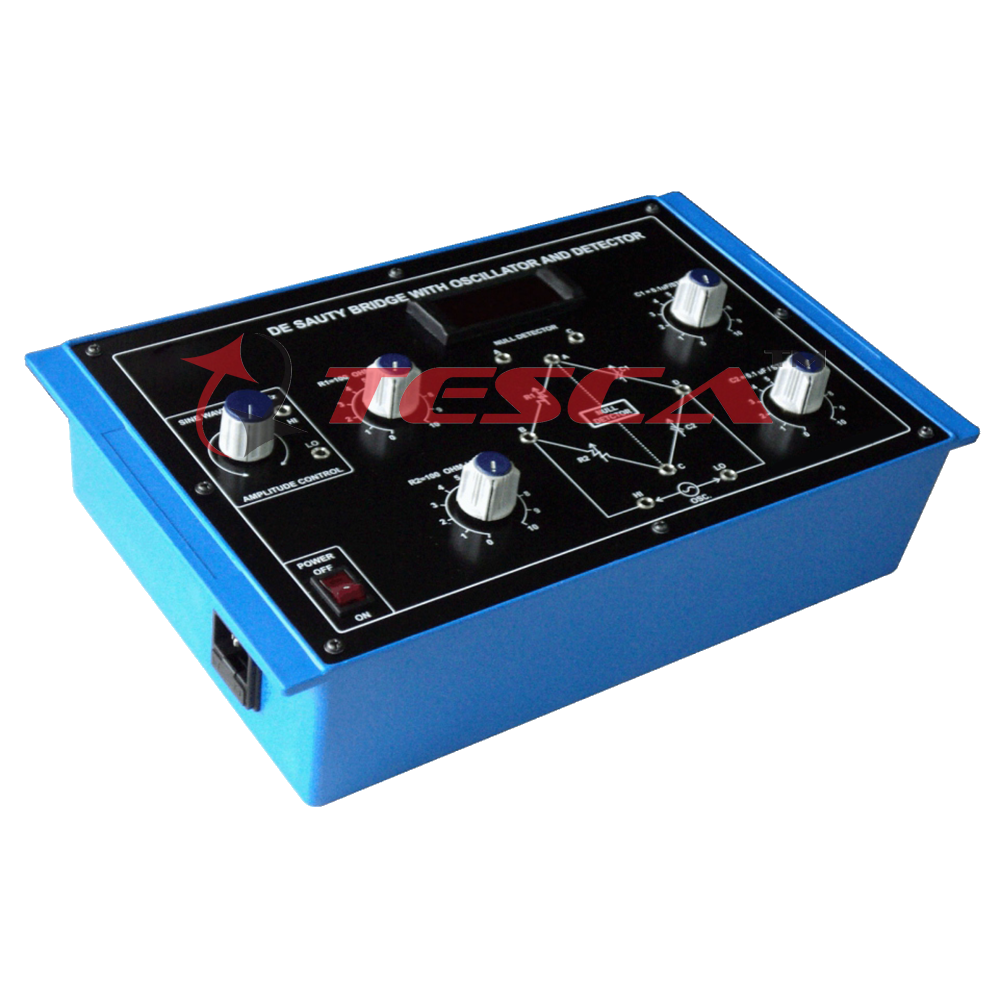
The board consists of the following built-in parts:
- ±12V D.C. at 100mA, IC regulated Power Supply internally connected.
- Sine Wave Oscillator with Audio Amplifier Frequency 1KHz ±3% output 0 – 2V
- 3½ Digit ditial null detector as a detection.
- Two Decade Capacitors, each with single dial in steps of 0.1uF total 1uF, to form the other two arms of the bridge.
- One Decade dial 100 Ohm total 1K, marked R1 & R2
- Mains ON/OFF switch, Fuse and Jewel light.
- The unit is operative on 230VAC ±10% at 50Hz.
- Adequate no. of patch cords stackable from rear both ends 4mm spring loaded plug length 50cm.
- Good Quality, reliable terminal/sockets are provided at appropriate places on panel for connections/ observation of wave forms.
- Strongly supported by detailed Operating Instructions, giving details of Object, Theory, Design procedures, Report Suggestions and Book References.
- Weight : 1.600 Kg. (Approx.)
- Dimension : W 340 x H 125 x D 210
List of Accessories:
- Patch cords 4mm length 50cm Red………01.
- Patch cords 4mm length 50cm black…….05.


Add comment