Table of Contents
Imagine a robotic arm that needs to perform a delicate task, such as picking up a small object or assembling a circuit board. How can we ensure that the arm moves to the correct position accurately?
The answer is the DC position control system. It is a type of feedback control system that regulates the position of a DC motor, ensuring movement to a desired position. The system uses a sensor to measure the motor’s actual position and compares it to the desired position. Based on the error between the two, the system adjusts the motor’s input voltage or current to drive it to the desired position.
All About DC Position Control System
This blog will explore how they work, the different control methods, the sensors used to measure position and the different types of DC motors used in the system.
What is DC Position Control System Trainer Board?
A DC position control system trainer board is used for training and experimenting with DC position control systems. It provides an efficient and effective way to learn and understand the fundamental principles of DC position control systems. This trainer board is a versatile and flexible tool for implementing various control algorithms and system configurations.
One can use it in many applications, such as robotics, automation, and machine tools, where precise and accurate control of the position of a DC motor is required. It involves feedback control, where a sensor provides a controller with information about the motor’s position. Then it adjusts the motor’s input voltage to achieve the desired position.
It includes a DC motor, a position sensor, and a control circuit mounted on a single board. The position sensor measures the actual position of the motor shaft and feeds this information back to the controller, which adjusts the motor’s input voltage to achieve the desired position. Program the control circuit with various control algorithms, including proportional-integral-derivative (PID) control, commonly used in DC position control systems. PID control calculates the error between the desired and actual positions of the motor and adjusts the input voltage based on this error.
It provides a hands-on learning experience for students and professionals to explore and experiment with different control algorithms and system configurations. Use it for testing and troubleshooting DC position control systems.
5 Uses of DC Position Control System Trainer Board?
1. Introduction to Position Control Systems
The trainer board introduces the basic concepts of position control systems, including the different types of control modes, position sensors, and actuator types.
2. Experimental Study of Position Control Systems
You can study and experiment with various position control systems. It allows the user to simulate different loads, disturbances, and input signals to test and evaluate the control system’s performance.
3. Evaluation of Feedback Control Strategies
Users can evaluate feedback control strategies like proportional, integral, and derivative (PID) controllers. The user can implement and tune the controllers and observe their effects using the built-in potentiometers.
4. Testing and Optimization of Control Algorithms
It is helpful for testing and optimizing control algorithms. The user can write custom algorithms in the microcontroller and test their performance by simulating different input signals and disturbances.
5. Industrial Applications
It can train students and professionals in applying position control systems in various settings. Especially useful for those involved in designing and implementing position control systems for robotics, automation, and other industrial applications.
Working Principle of DC Position Control System Trainer Board?
- It comprises a DC motor that drives a load connected to a potentiometer.
- The system receives a feedback signal from the potentiometer and compares it with the reference input signal to generate an error signal.
- The control algorithm processes the error signal and generates the control signal to the motor, which can adjust its speed and direction to align the potentiometer’s output position with the reference input position.
- A microcontroller and its associated circuitry provide the necessary control algorithm for position control.
- The microcontroller generates a pulse-width modulated (PWM) signal that controls the motor’s power supply. Furthermore, you can adjust it on the potentiometer feedback signal to maintain the desired position of the load.
- Various control parameters, like proportional, integral, and derivative gains, allow for fine-tuning of the system’s performance.
- It features multiple input and output ports to measure and monitor the system’s performance, including the input reference signal, feedback signal, and control signal.
Components of DC Position Control System Trainer Board?
1. Dc Motor
In order to drive the load, electrical energy is converted into mechanical energy.
2. Encoder
An encoder measures the position and velocity of the motor shaft and provides feedback to the controller for closed-loop control.
3. Motor Driver
The motor driver circuit is responsible for providing the necessary current to drive the motor and controlling the speed and direction of rotation.
4. Microcontroller
The microcontroller is the system’s brain, which receives input from the encoder and other sensors and sends output to the motor driver to control the motor.
5. Power Supply
This provides the necessary voltage and current to power the system components.
6. Interface Circuits
It connects the system to external devices, like a computer or a data acquisition system.
7. Potentiometer
A potentiometer manually adjusts the load’s position for testing and calibration purposes.
8. Control Knobs And Switches
It adjusts the system parameters, like the gain and damping of the controller.
9. Led Indicators
It provides visual feedback on the system’s status, like the motor direction and the error signal.
10. Breadboard
A breadboard allows for easy prototyping and testing of additional circuits and components.
DC Position Control System Trainer Board Setup?
- Unpack the board and ensure all the components are present.
- Connect the power supply to the trainer board. Ensure the power supply’s voltage and current rating are compatible with the trainer board.
- Connect the DC motor to the board.
- Connect the potentiometer to the motor shaft. The potentiometer measures the position of the motor shaft.
- Connect the encoder to the motor shaft. The encoder provides feedback on the position of the motor shaft.
- Connect the controller to the trainer board. The controller generates the control signal that drives the motor.
- Connect the CRO (cathode ray oscilloscope) to the trainer board. The CRO displays the output signal from the controller.
- Turn on the power supply and the controller. Make sure that the system is functioning properly.
- Run the experiment by varying the input signal to the controller and observing the response of the motor shaft position.
- Analyze the results of the experiment and make any necessary adjustments to the system.
5 Types of DC Position Control System Trainer Board?
Several DC Position Control System Trainer Boards types are available, each with unique features and capabilities. Here are the common types of DC Position Control System Trainer Boards:
1. Basic Dc Position Control System Trainer Board
This type of board provides a fundamental understanding of the DC position control system by demonstrating the concept of position control using a simple DC motor.
2. Advanced Dc Position Control System Trainer Board
This board offers more advanced features and capabilities than the basic board, including multiple input/output channels, a larger memory capacity, and the ability to interface with external devices. It is suitable for advanced training programs.
3. Programmable Dc Position Control System Trainer Board
This type of board allows users to program their control algorithms, making it ideal for students who want to develop their control algorithms and study their performance.
4. Pc-Based Dc Position Control System Trainer Board
This board interfaces with a computer, allowing real-time monitoring and control of the DC position control system. It is perfect for students who want to learn how to use software to control industrial processes.
5. Microcontroller-Based Dc Position Control System Trainer Board
It uses a microcontroller to perform the control algorithm. This type is perfect if you want to learn about embedded systems and how to program microcontrollers.
DC Position Control System Trainer Board Brochure?
- The brochure will highlight the purpose and main features.
- Technical specifications, such as input/output voltage ranges, maximum current, and position measurement resolution, may be included.
- It includes product images, photographs or illustrations, including accessories.
- The brochure may provide an explanation of laboratory experiments or industrial control systems.
- Specific features and benefits may be highlighted, like accuracy, ease of use, and flexibility for different control systems.
- User manuals, experiment guides, or software tools for educational use may be described.
- Information on customer support options, like technical support hotlines or warranty policies, may be provided.
- The brochure will include details of price, delivery options, and contact information for distributors.
DC Position Control System Trainer Board Price?
As prices can vary depending on the manufacturer, specific features, and included components, it’s best to check with other suppliers or manufacturers for accurate pricing information on the DC Position Control System Trainer Board.
Tesca Global DC Position Control System Trainer Board?
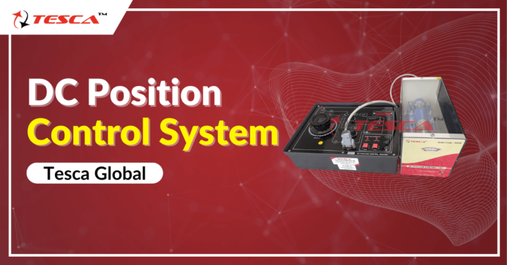
The Tesca Global DC Position Control System Trainer Board is a compact and easy-to-operate system designed for studying and operating a practical electromechanical angular-position-control system. Here are some of the features:
- The system features a controlled DC motor with a speed reduction gear- set, a potentiometric error sensor, and a tacho creator for haste feedback.
- The potentiometric error sensor uses special 360° revolution servo potentiometers to measure position.
- The tacho creator provides haste feedback to the system.
- It includes non-ideal parameters of amplifier and motor current, dead zone and countertraction, nonlinearity in the motor and gears, and mechanical fabrication defects.
- An erected mP- grounded waveform prisoner/ display system stores the control system’s step response in RAM and also displays it on a measuring CRO for further studies.
- The system internally provides all power inventories and step input signals.
- The panel features a 3 ½ number DVM for measuring signals.
- Calibrated dials for reference and affair position have a resolution of 1 °, and servo-potentiometers have a full 360 ° gyration.
- The system operates on 220V ± 10, 50Hz mains power.
Conclusion
The DC Position Control System Trainer Board is a must-have for professionals and students interested in learning the principles of position control systems. With various features and specifications, the board is user-friendly and perfect for conducting experiments.
With accuracy, quality, and reliability, Tesca Global‘s DC Position Control System Trainer Board stands out among the options available in the market. It is a perfect tool for students to experiment and learn practical electromechanical angular-position-control systems.
Tesca Global takes pride in delivering our customers the best products and services. Our DC Position Control System Trainer Board meets all the standards and specifications, ensuring its quality and durability. We believe that investing in this board is a great choice for students and professionals who are passionate about learning and growing in the field of control systems.
Don’t hesitate and place your order today!


Add comment