Table of Contents
To convert the resistance changes into voltage signals, the use of bridge circuits is quite common.
The most convenient part about this circuit is that the input can be directly put into the automatic control systems. Anderson Bridge makes it easy to obtain the balance point even with low-quality factor coils.
Today in this article, we are going to discuss Anderson Bridge and how the circuit works briefly here:
What is Anderson Bridge?
Anderson Bridge measures the accurate measurement of self-inductance of the circuit.
Image Credit: Circuit Glob
Anderson Bridge is the higher form of Maxwell’s inductance capacitance bridge. It is an AC Bridge. With the help of Anderson Bridge, we can determine the self-inductance of an inductor in the circuit.
The unknown inductance is compared with the standard fixed capacitance in the Anderson Bridge, which is connected between the two arms of the Bridge. The output from Anderson Bridge is accurate. Repeated balancing of the Bridge is also not required in Anderson Bridge.
Theory of Anderson Bridge:
Let us focus on the theory of Anderson Bridge here briefly:

The value of the unknown impedance (self/mutual inductance of inductors or capacitance of capacitors accurately) is measured by AC Bridge. Anderson Bridge is a Bridge that measures self-inductance, and in Anderson Bridge, a large number of AC Bridge is present and is also a modified Wheatstone Bridge.
It is also a modified version of the Maxwell bridge. Repeated balancing is not required in Anderson Bridge, and capacitors and resistors are used to measure the coil’s inductance.
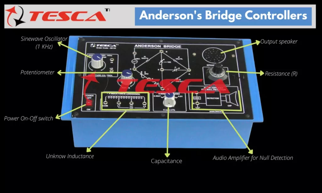
Apparatus that are required for Anderson Bridge are resistance boxes, capacitor, headphone, signal generator, inductance coil, and connection wire.
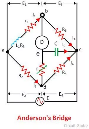
Anderson Bridge contains four arms they are- ab, bc, cd, and ad. It can find out the value even at a low range.
In this, bc, cd, and the ad are purely resistive arms and are connected in series with the circuit, and ab consists of unknown inductance with resistance. The variable resistor and static capacitors are connected in series form and placed parallel to the cd arm. In the terminal, a and b voltage source is applied.
Applications of Anderson Bridge:
Anderson bridges are used for measuring the self-inductance of the coil. It is also used to find the inductive reactance value of the coin even at a specific frequency.
With the help of the Anderson Bridge, components such as resistance, inductance, capacitance, etc., can be measured. It is used for determining the accurate capacitance in terms of inductance.
With the help of Anderson Bridge, rate determination of inductance can be done within the mm range.
Measurements by Anderson’s Bridge:
Anderson bridge is an instrument used for measuring the self-inductance of a coil.
Samuel D. Anderson invented it in 1873. A differential form of this instrument is still widely used today for this purpose, though more advanced tools are also available.
The ability of any coil to induce voltage from a magnetic field is referred to as self-inductance. And one of the most critical parameters that determine how large the self-inductance is is the shape or geometry of the coil.
Anderson bridge is used to measure the resistance or conductance of a sample. It can be made from any material, and all that matters for it to work is that it has two conductive terminals and one non-conductive terminal. It can be used as an alternative to a Wheatstone bridge and Maxwell bridge.
How to measure unknown inductance with Anderson Bridge?
The process of Anderson Bridge is as follows:
First of all, the voltage should be applied from the signal generator by setting an arbitrary frequency. After doing this, you need to select the value of the coil from the set inductor value option on the device.
After setting the value, you need to switch on the supply so that the device can get Milivoltmeter deflection.
Now you need to set the values from the resistance and capacitance box. You need to set these values in such a way that it should achieve the particular values to “Null.”
After applying these values, you need to absorb the device until the Milivoltmeter pointer reaches the “Null” value.
After checking the null value, you need to switch to the measure inductor value option and press the stimulate option on the device. Now you need to observe the inductor value and its unknown internal resistance. Along with that, observations of the dissipation factor should also be done.
Anderson bridge experiment readings:
Anderson bridges are used for measuring the self-inductance of a coil, and it is an AC Bridge. With the help of standard capacitors and resistors, the measurement is enabled, and it omits the requirement of repetition of balancing the Bridge.
It is a better modification to the Maxwell Bridge. In this Bridge, one arm consists of the unknown value of the inductor, which is known with the resistance series Lx. The resistance one of the which country is the resistance of the inductor. On the other hand, the standard of the capacitor is identified with the series of R1, R2, R3, R4. The standard of the capacitor is capacitance C. These values are non-inductive in nature.
The Anderson Bridge method is useful in measuring the capacitors. When the capacitor is not used correctly, then the value of inductance doesn’t change, but the value of R1 does change. This is possible if the calibrated self-inductance is available. The equation that we get at the end is R1= R2R3/R4.
We get the unknown inductor’s value with Anderson Bridge’s help by applying the principle of a null value. In this experiment, the signal of the generator frequency is set at a frequency or range that is audible.
After this, the R 1 and r are adjusted with the null detector at a minimal sound range. Now the value of R1 and R2 should be obtained with the help of the multimeter, and by using the formula, the unknown value of the inductance is derived.
This is how the non-value can be identified, and by setting the different values of the standard capacitor, the experiment can be repeated.
Calculation: Anderson’s Bridge Formula
Working of Anderson’s Bridge:
It is an AC Bridge that is used for measuring the self-inductance of a coil. With the help of the resistor and using the standard capital, the measurement of the coil’s inductance is enabled by Anderson Bridge.
Anderson bridges a modified version of Maxwell Bridge which also uses the same process of obtaining the value of self-inductance by comparing the value with the standard capacitor.
In Anderson Bridge, the repetition of the balance of the bridges is not required. In this Bridge, fixed capital is used, unlike other bridges in which a variable capacitor is used.
The circuit consists of a capacitor and resistor in series with the coil under test and an oscillator tuned to resonate at the resonant frequency of the speaker.
It then measures the self-inductance by measuring the impedance of this resonant circuit with a digital multimeter (DMM) and uses this value to calculate inductance. In the Anderson Bridge, there is no standard variable capacitor. A fixed value capacitor can be used in this circuit.

Know more about Tesca’s Anderson Bridge.
Problems with Anderson’s Bridge:
Recent cue to the reason that it has additional junction point. Here are some of the problems that are associated with Anderson Bridge:
- The problem with Anderson Bridge estate compared to other Bridge Anderson Bridge is complicated when it comes to the number of components used in it.
- To avoid the effect of stray capacitances, Anderson Bridge cannot be shielded.
- In comparison to the other Bridges, the balance equations used in Anderson Bridge are complicated to derive.
- In comparison to Maxwell Bridge calculation, the balance Calculation and Anderson Bridge are way more complicated.
Anderson Bridge Method:
In the Anderson Bridge, the measurement of the value of unknown self-inductance or capacitance of capacitors is done accurately. In Anderson Bridge, the measurement of self-inductance of the coil is running with ac bridges that are available in abundance in this Bridge.
This Bridge is a modification of the Maxwell bridge and Wheatstone Bridge. With the help of Anderson Bridge, the measurement of self-inductance of the coil is done by using capacitors and resistors. This does not require any repetitive balance.
In Anderson Bridge, The Bridge is balanced with the help of a moving coil galvanometer and AC source by a battery. In this, the headphones H are replaced, and it was steadily with the help of the current of the coil, which is done by adjusting the variable resistance.
The inductive balance in the bridges is obtained by using the current of the headphone and ac source, and thus a steady balance is received.
Anderson’s Bridge Physics:
In the Anderson bridge, the circuit of the Bridge is used to measure the components and self-inductance such as capacitance, inductance, resistance, and so on. When we talk about the simplest form of a bridge, then the circuits in the Bridge consist of four types of resistance impedance arms that form is Circus that is closed.
On the opposite nodes of the circuit current source is applied, and also, on the other two nodes, a current detector is connected. Anderson Bridge works on the principle of induction principle.
The method that is used in this Bridge is a comparison method known as “The Bridge Balance Condition at Zero Voltage.” In this method, the values of an unknown component are compared with the help of bridge circuits by applying the accurately known standard component.
The accuracy of the component depends upon the bridge circuit instead of the null indicator.
This Bridge is known to measure the unknown impedance. The brush consists of 4 impedance and is connected with the AC supply and current balance detector.
The detectors which are commonly used in these bridges are Headphones, vibration galvanometers, and amplifier circuits that are turnable.
As the circuit follows the null response principle, then attaining the condition is of utmost importance here. It can be obtained by varying one of the bridge arms.
The self-inductance of the components is mainly in the form of polar. The polar has a magnitude and a phase angle value.
Range of Anderson Bridge:
Anderson Bridge is an instrument through which the measurement of values of inductance and the quality factor can be identified. It can be identified with a low range of less than 1. The self-inductance value is found out between the two coils.
It is a modification of the two Bridges: captive Bridge and Maxwell inductance Bridge. The self-inductance in this method is measured with the help of a standard capacitor. It is done to get the precise measurement.
This measurement is done to get the accurate self-inductance measurement of unknown coils over a wide range of values.
Some of the balance detectors that are used in Anderson Bridge are headphones with a frequency of 250 Hz up to 4k Hz, vibration Galvanometer at the frequency of 5 Hz up to 1000 Hz, and amplifier circuit ETA turnable with the range of 10 Hz up to 100 Hz.


Add comment