Table of Contents
“A Resistance Capacitance (R.C.) Coupled Amplifier is a multistage amplifier circuit extensively utilized in electronic circuits.” The several stages of the Amplifier are connected in this configuration utilizing a resistor–capacitor combination, this configuration is known as an R.C. Coupled amplifier.
In an RC coupled amplifier, the input signal is applied to the base of the input transistor (or the emitter in the case of a common-base amplifier). The transistor amplifies the signal and applies it to the input capacitor, which blocks the DC component of the signal and passes the AC component to the output stage. The output stage amplifies the signal further and applies it to the load.
RC coupled amplifier have a relatively simple circuit configuration and are easy to design and build. They are also relatively inexpensive to produce, which makes them a popular choice in many electronic applications. However, they do have some limitations, such as a relatively low voltage gain and poor frequency response at high frequencies.
RC Coupled Amplifier: Uses, Working Principles, Components, Setup, Types & Price
RC coupled amplifier are a useful and widely used type of amplifier that are suitable for a wide range of applications, including audio amplifiers, radio frequency (RF) amplifiers, and instrumentation amplifiers. Let’s read about RC Coupled Amplifier uses, working principles and components etc.
What is RC Coupled Amplifier Training Board?
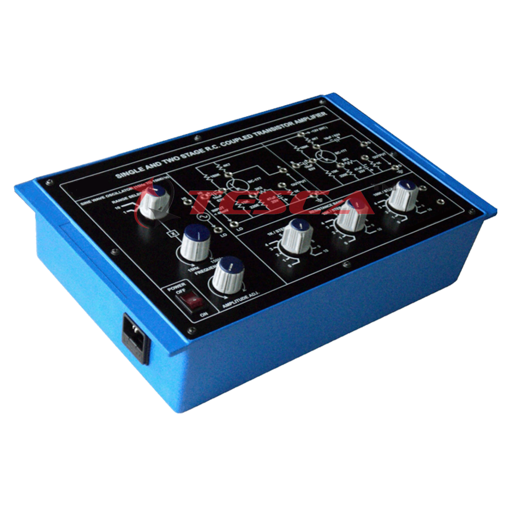
“An RC coupled amplifier training board is a type of educational tool that is used to teach students about the principles of amplifier circuit design and operation”. It is typically a small, self-contained unit that includes all the components needed to build and test an RC coupled amplifier circuit, including transistors, capacitors, resistors, and other passive components.
The training board typically includes a set of instructional materials, such as a manual or tutorial, that explains how to build and test the amplifier circuit. It may also include a set of test probes and other measurement equipment, such as an oscilloscope or multimeter, to allow students to measure and analyze the performance of the amplifier.
RC coupled amplifier training boards are typically used in electronics engineering courses or other educational programs where students need to learn about amplifier circuits and their applications. They provide students with hands-on experience building and testing amplifier circuits, which helps them to better understand the principles of amplifier operation and design.
Uses of RC Coupled Amplifier Training Board
An RC coupled amplifier training board is a useful educational tool that is used to teach students about amplifier circuit design and operation. It is typically used in electronics engineering courses or other educational programs where students need to learn about amplifier circuits and their applications.
Some of the main uses of an RC coupled amplifier training board include:
- Learning about amplifier circuit design and operation: The training board provides students with hands-on experience building and testing an amplifier circuit, which helps them to better understand the principles of amplifier operation and design.
- Practicing amplifier circuit design and testing techniques: The training board allows students to practice building and testing an amplifier circuit, which helps them to develop their skills in these areas.
- Analyzing amplifier performance: The training board may include measurement equipment, such as an oscilloscope or multimeter, which allows students to measure and analyze the performance of the amplifier circuit.
- Completing class assignments and projects: Students may use the training board as part of class assignments or projects, where they are required to build and test an amplifier circuit.
Overall, an RC coupled amplifier training board is a valuable educational tool that helps students to learn about amplifier circuit design and operation and to develop their skills in these areas.
Working Principle of RC Coupled Amplifier Training Board
The working principle of an RC coupled amplifier training board is based on the principles of amplifier circuit design and operation. An RC coupled amplifier is a type of amplifier circuit that uses capacitors to couple the input signal to the output stage. The input stage of an RC coupled amplifier is typically a common-emitter or common-base amplifier, and the output stage is typically a common-collector or emitter follower configuration.
In an RC coupled amplifier, the input signal is applied to the base of the input transistor (or the emitter in the case of a common-base amplifier). The transistor amplifies the signal and applies it to the input capacitor, which blocks the DC component of the signal and passes the AC component to the output stage. The output stage amplifies the signal further and applies it to the load.
The training board includes all the components needed to build and test an RC coupled amplifier circuit, including transistors, capacitors, resistors, and other passive components. It also includes instructional materials and measurement equipment, such as an oscilloscope or multimeter, to allow students to build and test the amplifier circuit and analyze its performance.
Overall, the working principle of an RC coupled amplifier training board is based on the principles of amplifier circuit design and operation, and it provides students with hands-on experience building and testing an amplifier circuit to better understand these principles.
Components of RC Coupled Amplifier Training Board
An RC coupled amplifier training board typically includes a set of components that are used to build and test an RC coupled amplifier circuit. The specific components included in the training board may vary depending on the specific design of the amplifier and the intended application. However, most training boards will include the following components:
- Transistors
- Capacitors
- Resistors
- Other passive components
- Instructional materials
- Measurement equipment
Overall, the components of an RC coupled amplifier training board are designed to allow students to build and test an amplifier circuit and to learn about the principles of amplifier operation and design.
RC Coupled Amplifier Training Board Setup
The setup of an RC coupled amplifier training board will depend on the specific design of the amplifier and the intended application. However, most training boards are designed to be easy to use and set up, and will include instructions or a tutorial on how to build and test the amplifier circuit.
Here is a general overview of the steps involved in setting up an RC coupled amplifier training board:
- Assemble the components
- Connect the input and output signals
- Set the bias points
- Connect the measurement equipment
- Test the amplifier
Overall, the setup of an RC coupled amplifier training board involves assembling the components, connecting the input and output signals, setting the bias points, and connecting any measurement equipment. Once the circuit is set up, you can test the amplifier and make any necessary adjustments to optimize its performance.
Types RC Coupled Amplifier Training Board
Single Stage R.C. Coupled Amplifier:-
A single stage RC coupled amplifier is a type of amplifier circuit that uses a single transistor and a pair of capacitors to amplify an input signal. It is called an RC coupled amplifier because the capacitors are used to couple the input signal to the output stage of the amplifier.
Two-Stage RC Coupled Amplifiers:-
A two-stage RC coupled amplifier is a type of amplifier circuit that uses two stages of amplification to amplify an input signal. The first stage is typically a common-emitter or common-base amplifier, and the second stage is typically a common-collector or emitter follower configuration. The two stages are connected using a pair of capacitors, which are used to couple the input signal to the output stage.
RC Coupled Amplifier Training Board Brochure
RC Coupled Amplifier Training Board Price
Price: Rs 6000 for the Electrical Analog Two Stage Rc Coupled Amplifier Trainer Board, Model No. 4509.
Read also: Optoelectronic Experimental Training Board: Guide by TescaGlobal.
Tesla Global Single and Two Stage RC Coupled Amplifier Training Board
This experimental training board focuses on two-stage RC coupled transistor amplifiers as its primary topic of study.
Science and engineering students can gain a lot from the time spent working on these boards.
Object:
- An Examination of the Characteristics of a Two-Stage R-C Coupled Transistor Amplifier
- Study how the behaviour of an amplifier changes as it is overloaded.
- Conduct a frequency response analysis on the individual amplifier as well as on the cascade amplifier.
- Find out the input and output impedances of each stage, as well as the total impedance of the cascade amplifier.
Features:
The following parts are essential to the functioning of the board:
- power supply regulated by an integrated circuit, 12V DC.
- There is a total of two PNP transistors in this circuit.
- Additional electronic components, in an adequate number.
- A power switch, a safety fuse, and a brilliant jewel bulb are included.
- 230 volts of alternating current power the device. 50 Hertz and within 10% of the mains.
- A sufficient quantity of stackable patch cords, each of which has a 4mm spring-loaded plug attached to both ends and has a total length of half a metre.
- When it comes to making connections and analysing waveforms, the control panel is equipped with connectors and sockets that are of a high quality and can be relied upon.
- Supported by a comprehensive collection of operating instructions that detail the object, theorem, design process, report suggestions, and book references.


Add comment